Last updated on March 26th, 2024 at 04:36 pm
The Arduino Pro Mini is a microcontroller board based on the microchip ATmega328. The board consists of 6 analog inputs, 14 digital input/output pins (of which 6 can be used as PWM outputs), a reset button, an onboard 8Mhz resonator, and holes for mounting pin headers.
A six-pin programming header can be connected to an FTDI cable or Spark fun breakout board to provide USB power and program the board. Atmega 328-based Arduino Pro Mini pinout and specifications is given in detail in this post.
There are two different versions of the Arduino Pro Mini: one runs at 3.3V and 8 MHz, and the other one at 5V and 16 MHz.
Note A: Older version of the Pro mini has ATmega 168 instead of ATmega 328.
Note B: Arduino Pro mini does not have a USB port. So you will need an FTDI adapter to program it. There is a separate programming header with 6 pins for FTDI connection. Also, it does not come with headers, so you have to solder header pins to the board first.
Table of Contents
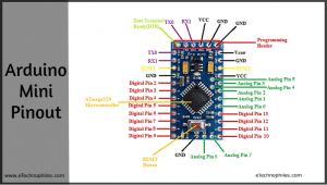
Arduino Pro mini pinout
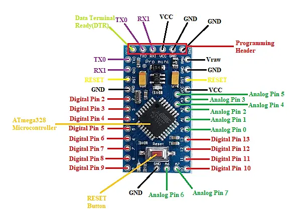
The functions of different pins on the Arduino Pro mini pin diagram are shown in the table below. We have discussed the detailed pinout at a later stage in this article.
| Pin Type | Pins | Total pins |
| Power Supply Pins | VCC, RAW, GND | 8 |
| Digital Pins | 0 – 13 | 14 |
| PWM Pins | 3, 5, 6, 9, 10, 11 | 6 |
| Analog Pins | A0 – A7 | 8 |
| Serial Pins | RXD: 0, TXD: 1 | |
| External Interrupt Pins | 2, 3 | 2 |
| SPI Pins | SS: 10 MOSI: 11 MISO: 12 SCLK: 13 | 1 SPI interface |
| I2C Pins | A4 :SDA A5:SCL | 1 I2C protocol |
| Built-in LED Pin | 13 |
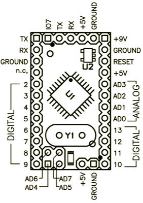
Arduino Pro mini pin diagram layout (official)
a) Mini 03 (older version)
b) Mini 04 and 05 (New version)
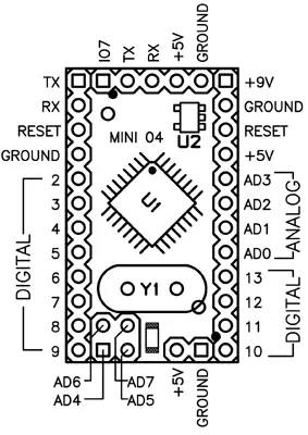
NOTE: the ground on the left has moved down one pin.
Image Source: Arduino Website
Specifications
Given below are the technical specs of Arduino Pro Mini.
| Microcontroller | ATmega328(latest version) |
| Operating Voltage | 5V and 3.3V |
| Input Voltage | 5 – 12 V (5V model) and 3.3 – 12 V(3.3V model) |
| Digital I/O Pins | 14 Pins (6 are PWM output pins) |
| Analog Input Pins | 6 Pins |
| DC Current per I/O Pin | 40 mA |
| Flash Memory | 32 kB (0.5 kB is taken by bootloader) |
| SRAM | 2 Kbytes |
| EEPROM | 1 Kbytes |
| Clock Speed | 16 MHz (5V model) and 8 MHz (3.3V model) |
Note: The older version of the Pro Mini had the following specs that are different from the latest version:
- Microcontroller- ATmega 168
- Flash memory: 16 KB
- SRAM: 1 KB
- EEPROM: 512 bytes
Are you a beginner? Can't decide which book to read? Check out this article on Best Arduino Books for beginners
Arduino Pro mini pinout details
ATmega328 microchip
The ATmega328 microcontroller is a high-speed, power-efficient AVR 8-bit microcontroller. It consists of 32 KB of flash memory for storing the program code (0.5 KB is used for storing the bootloader), 2 Kbytes of SRAM, and 1 Kbytes of EEPROM.
RESET Button
This button generates a low-level signal at the pin which is used to reboot the microcontroller.
Power Supply pins
RAW: RAW is the unregulated input voltage that is supplied to the regulator. The supplied voltage at this pin can range anywhere between 3.4 to 12V.
VCC: It is the regulated voltage of 3.3V. We can change the voltage supplied voltage to 5V depending on the versions of the board.
GND: There are three GND (Ground) pins present on the Arduino Pro Mini board.
Digital Pins
There are 14 digital I/O pins (0-13) out of which 6 are PWM pins. The Arduino digital pins can read/output only two states: when there is a voltage signal and when there is no signal. This kind of input/output is usually called digital (or binary) and these states are referred to as HIGH or 1 and LOW or 0.
These digital pins can be configured as an input or output using the pinMode (), digitalWrite (), and digitalRead () functions.
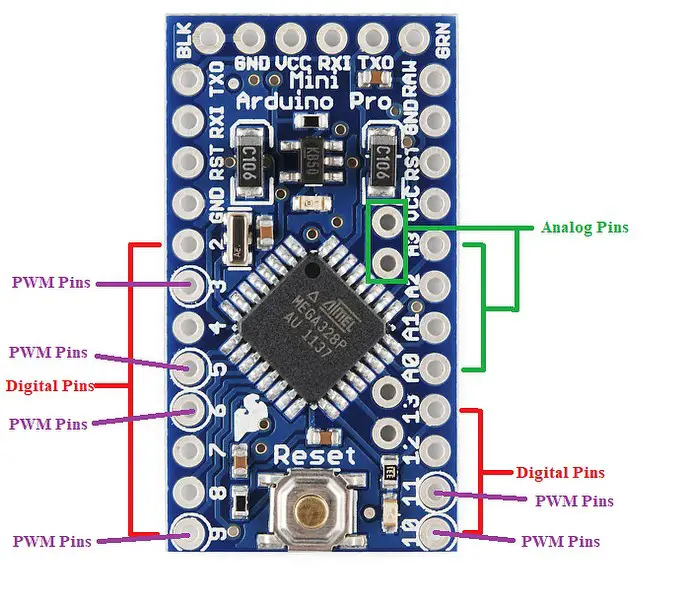
PWM pins
There are six pins from the set of digital pins that are PWM (Pulse Width Modulation) pins, numbered 3, 5, 6, 9, 10, and 11.
Every one of these digital pins can generate a Pulse Width Modulation signal of 23-bit resolution. We can generate the PWM signal using the analogWrite() function. Either pin provides 8-bit PWM with analogWrite ().
Analog Pins
Arduino UNO has 6 analog pins, whereas Mini has eight analog pins numbered from A0 to A7. You can connect up to 8 analog/digital sensors to the board.
The function of Analog pins is to read the value of the analog/digital input used in the connection. Each of these analog pins has an inbuilt ADC of resolution of 210 bits (so it will give 1024 values).
Note: Analog pins A4 and A5 are behind the Analog pins A2 and A3. These are placed in a tight spot to achieve a small form factor.
UART Pins (RX and TX)
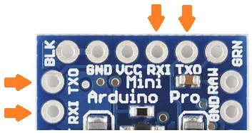
These pins are used for serial communication. The pins are used to receive (RX) and send (TX) TTL (Transistor-Transistor Logic) data. These pins are connected to the TX-0 and RX-1 pins of the six-pin block of the board.
Note: The UART pins can also be used as digital I/O pins.
External interrupt (2 and 3)
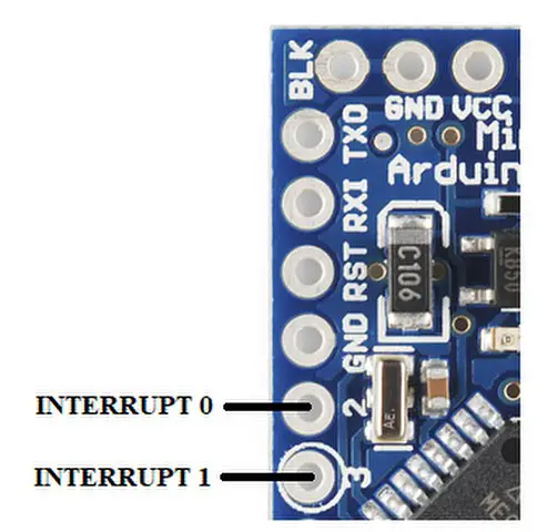
These pins can be used to trigger an interrupt on a low value, a rising or falling edge, or a change in value.
SPI Pins
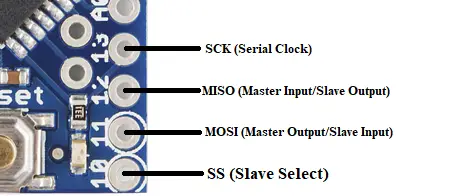
It stands for Serial Peripheral Interface. These pins are used by the board to communicate with one or more peripheral devices quickly. There are three common lines to all the peripheral devices:
- SCK-It stands for Serial Clock. These are the clock pulses, that are used to adjust the transfer of data.
- MISO-It stands for Master Input/ Slave Output. This data line in the MISO pin is used to send the data to the master.
- MOSI-It stands for Master Output/ Slave Input. This line is used for transmitting data to the peripheral devices.
- SS-It stands for Slave Select. This line is used by the master. It acts as the enable line. When a device’s SS pin value is set to LOW, it can communicate with the master. When its value is HIGH, it ignores the master command. This allows us to have several SPI peripheral devices sharing the common MISO, MOSI, and CLK lines.
I2C pins
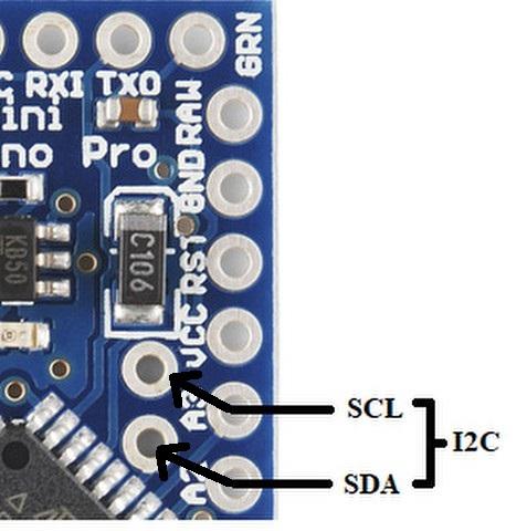
It is the two-wire serial communication protocol. It stands for Inter-Integrated Circuits. The I2C uses two lines to send and transmit data: a serial clock pin uses (SCL) and a serial data (SDA) (SDA) pin.
- SCL(A4)-It stands for Serial Clock. It is defined as the line that transmits the clock data. It is used to adjust the shift of data between the two devices. The Serial Clock is initiated by the master device.
- SDA(A5)-It stands for Serial Data. It is defined as the line used by the slave and master to send and receive data. That’s why it is known as a data line, while SCL is called a clock line.
LED: In the board, there is a built-in LED connected to digital pin 13. When this pin is set to HIGH or 1, the LED turns ON. When the pin is set to LOW or 0, the LED turns OFF.
RESET: This pin is used to reset the microcontroller.
DTR (Data Terminal ready): This pin is used to reset the board and enter the bootloader for programming the Arduino pro-mini.
Where to buy Arduino Pro Mini?
You can get the original Arduino Pro Mini board from different stores. But if you want to get it from Amazon, we recommend the following sellers:


FAQs
How much Power does Arduino Pro mini use?
While running a blink sketch, the ProMini (5V board) takes around 25mA current. On the other hand, the ProMini (3.3V board) takes around 8mA current. So we can see that ProMini (3.3V board) consumes less current.
You can check out this article to get a detailed insight into this topic
How many pins does Arduino Pro mini have?
It has a total of 33 pins.
How much RAM does Arduino Pro mini have?
Arduino Pro mini has 2 KB of SRAM.

Hi, Great article but the SCL & SDA are incorrectly marked at A2 & A3 not A4 & A5! (The two holes further into the board, the screenprint is on the rear)
Hi,
Thank you for pointing out the mistake. The image has been updated 🙂
Beautiful pictures but many stupid mistakes!
Look at the silkscreen of the first color-picture: You have wrong numbers (NOT A0!) on analog port A6 and analog port A7.
Also you count the numbers of digital pin 10 & 11 &12 & 13 in the wrong direction!
There are also Pro Mini’s which do have not the ATmega 328P but the ATmega168P installed. I don’t know if these are official Arduino versions, but the Arduino IDE in fact does support these.
Hi Gunther,
Thank you for pointing out the errors. We really appreciate it 🙂
All the errors are resolved now.