Last updated on March 18th, 2024 at 06:33 pm
An IC 555 timer is a versatile integrated circuit that can be used for various purposes in electronic circuits. Engineer Hans Camenzind first introduced the 555 timer in 1972, and it has since become one of the most popular ICs on the market.
Its popularity is due to its simple design and wide range of capabilities. It functions as an oscillator, a square-wave generator with a duty cycle that ranges from 50% to 100%, and a timer.

The image below shows that the three 5k ohm resistors coupled in a voltage-divider configuration gave rise to the name “555 timer”. Since the complete internal circuit consists of over 16 resistors, 20 transistors, 2 diodes, a flip-flop, and many other circuit components, a simplified representation of the internal circuit is provided below for better comprehension.

The 555 timer is a dual in-line package (DIP) IC with 8 pins. Additionally, there are two 555 timers inside the 556 IC which is available as a 14 DIP, and four 555 timers in the 558 quadruple timer, which is an IC and is available in the market as a 16-pin DIP.
Table of Contents
555 Timer pinout
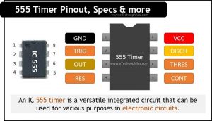
555 timer IC is an 8-pin IC. This indicates that there are 8 separate pins: Ground, Trigger, Output, Reset, Control Voltage, Threshold, Discharge, and Supply.

The pin names and the roles they play in a circuit are provided in the table below.
| Pin No. | Pin Name | Description |
|---|---|---|
| 1 | Ground(GND) | This pin serves no unique purpose at all. It has the standard ground connection. This pin needs to be connected to the ground for the timer to work. |
| 2 | Trigger(TRIG) | The trigger pin is number two. The timer begins when the voltage on pin 2 drops to less than one-third of the supply voltage because the trigger is an active low trigger. The output on pin 3 becomes high when the 555 is activated using pin 2. |
| 3 | Output Pin(OUT) | The output pin is pin number 3. The output of a 555 timer is digital in nature. Either way, it is high or low. The output might be high, which is near to the supply voltage connected to pin 8, or low, which is extremely close to 0V. The load that you want the 555 timer to power is connected to this pin. |
| 4 | Reset Pin(RST) | The reset pin is pin 4. The timing action of the 555 timer can be restarted using this pin. Like the trigger input, this input is an active low. Thus, for the 555 timer to work, pin 4 needs to be linked to the supply voltage. If we connect this pin to ground, the 555 timer will get interrupted and it won’t start again until pin 2 is used to trigger it once more. |
| 5 | Control Voltage(CTRL) | Pin-5 is the control voltage pin used to control the pulse width of the output waveform and also the voltage levels of threshold and trigger pin. The output waveform is modified when an external voltage is applied to this pin. This pin is simply directly connected to the ground in 555 timer circuits, typically via a tiny capacitor of approximately 0.01uF. This capacitor reduces variations in the power supply voltage that can affect the timer’s functionality. |
| 6 | Threshold | The threshold pin is 6. Its function is to track the voltage across the capacitor that pin 7 has discharged. The timing cycle is completed, and the output on pin 3 becomes low, when this voltage exceeds 2/3 of the supply voltage (Vcc). |
| 7 | Discharge | The discharge pin is number 7. An external capacitor that controls the time interval in combination with a resistor is discharged via this pin. In the majority of designs, pin 7 is linked to ground through a capacitor and to the supply voltage using a resistor. |
| 8 | Supply(VCC) | This pin supplies the power to the IC. A voltage of at least 4.5V and not more than 15V is required. 555 timer circuits are frequently powered by a single 9V battery. |

Specifications
- From + 5 V to + 18 V, a wide range of input supply voltages can be given to the 555 timer.
- The maximum load current is 200mA.
- There is a 600 mW maximum power dissipation rating.
- The operating temperature ranges from 0 to 75 °C.
- Due to its high current output, the o/p of a 555-timer IC can drive a TTL (transistor-transistor logic).
What are the different operating modes of 555 Timer?
IC555 has a total of 3 operating modes: Monostable, Astable, and Bistable. Each of these modes needs an external circuit for a specific output:
- Monostable: Single pulse of fixed length
- Bistable: Either High or Low output pulse
- Astable: Continous output pulse (…High-Low-High-LOW….)
1. Monostable mode

In response to a trigger input, such as a push button, a monostable circuit generates a high pulse of a predetermined length depending upon the capacitor and resistor value. The term “monostable,” which means “one stable state,” refers to the circuit’s output, which remains in the low state until a trigger input is present.
This circuit is perfect for an exhibition model’s “push to operate” mechanism. A model’s mechanism can be started by a visitor pressing a button, and it will shut off on its own after a predetermined amount of time.
2. Bistable mode(or Schmitt trigger)
A Schmitt Trigger, also known as a bistable mode, has two stable states: high and low. The circuit’s output enters the high state when the Trigger input is made low. The output enters the low state when the Reset input is made low.
The use of this kind of circuit in an automated model railroad system is perfect when the train needs to travel back and forth over the same section of track. At each end of the track, a push button (or reed switch with a magnet on the underside of the train) would be installed such that when the train hits one, it will either trigger or reset the bistable.
The 555’s output would operate a DPDT relay wired as a reversing switch to switch the direction of electricity flowing to the track, which would turn around the direction of the train.
3. Astable mode

The term “astable” refers to a circuit that lacks a stable state. A “square” wave is produced that alternates between high and low states continuously and without human input.
By turning a motor on and off at set intervals, this kind of circuit could be utilized to provide a device with irregular motion. It can be used as a “clock” pulse for other digital ICs and circuits as well as to flash LEDs and lamps.
Applications
The following are some typical applications and uses of a 555 timer:
- Pulse, Waveform, and square wave generation
- As a monostable and astable multivibrator
- Time delay generation, precision timing, and sequential timing
- Schmitt trigger
- Stepped tone, tone burst generator & linear ramp generation
- Used in tachometers & temperature measurement
- In DC to DC Converters and DC Voltage Regulators
- Used for quad timer applications and as a flip-flop element
- It can be used for voltage-to-frequency converter
- It is also used in Frequency Divider
Datasheet
Given below is the datasheet of the 555 timer:
5 Cool Project Ideas Using 555 Timer IC
1. Motion Detector Using NE555 Timer
This circuit is built on a passive infrared (PIR) sensor, which turns a gadget on when someone approaches it. It can be used to identify theft or unlawful access to a building or restricted area. When a person approaches the area where it is located, it can also switch on lights. Among the uses for this circuit are security systems, hallway lighting, and bathroom lighting.
2. Checking Highway Speed
The highway traffic police may find this speed checker useful. It will not only give a digital reading of a car’s speed but will also sound an alarm if the speed limit for the highway is exceeded.(Read more)
3. 555 IC Model Traffic Lights Circuit
This is a model traffic light circuit. This circuit turns on a green LED, maintains it on for a while, then briefly turns on a yellow LED before turning on a red LED that remains on for almost the same amount of time as the green LED.(Read more)
4. Circuit for Doubling DC Voltage Using a 555 Timer
This circuit accepts a DC input voltage of any value between 5 and 15 volts and outputs double the input voltage.(Read more)
FAQs
Why IC 555 is called so?
The ‘555’ in the IC’s name comes from the three 5-kiloohm resistors used in its internal voltage divider network.
Is 555 timer analog or digital?
The 555 timer IC is primarily an analog device, although it is often used in digital circuits as well. Its internal circuitry is based on analog components such as resistors, capacitors, and comparators. However, it can be configured to operate in various modes, including astable, monostable, and bistable, which can generate digital-like output signals such as square waves or pulses.
What are the three modes of 555 timer IC?
Monostable, Bistable and Astable are the three operating modes of 555 timer.
What is the maximum frequency of a 555 timer?
The maximum frequency of the IC typically ranges from tens of kilohertz to several megahertz, depending on factors such as the values of the external resistors and capacitors used in the circuit, as well as the characteristics of the specific 555 timer IC being used.