Last updated on January 20th, 2026 at 11:29 am
This is a simple yet effective RPM tachometer using Arduino UNO and an IR sensor. It counts the revolutions of a rotating object using interrupts and displays the RPM on an OLED screen. This adaptable tool is useful for controlling and monitoring machines, making it an excellent addition to a variety of projects and industries.
Table of Contents
How does this tachometer work?
Given below are the series of steps this tachometer goes through to display the motor speed.
1. Sensor setup: First, place an infrared sensor near a rotating product with a reflecting marking or gaps. The IR sensor recognizes the marker as it passes in front of it.
2. Interrupt handling: The Arduino board is set up to respond to falling edge interrupts. When an interruption occurs, it increases a counter, effectively counting half a revolution.
3. RPM calculation: To obtain the RPM (Revolutions Per Minute), this formula is applied:
RPM = (Counter / 2) * 60
Here, the division by 2 stands for counting half-revolutions in the one-second interval, and multiplying by 60 converts it to RPM.
4. Display update: The calculated RPM value is displayed on the OLED screen. The display updates every second, giving real-time RPM readings.
5. Continuous monitoring: This process is repeated continuously and we get the RPM of motors accurately.
Components required
- Arduino Nano or Arduino Uno
- IR Sensor
- 0.96 inch OLED Display
Introduction to IR sensor
An infrared sensor is an electronic device that emits light to detect an object in its surroundings. An IR sensor can detect motion as well as measure the heat of an object.
Typically, all objects in the infrared range emit some type of thermal radiation. These radiations are undetectable to human eyes, but an infrared sensor can detect them.
The emitter is a simple infrared LED (Light Emitting Diode), while the detector is a simple infrared photodiode. The photodiode is sensitive to infrared light of the same wavelength as the IR LED.
When infrared light strikes a photodiode, the resistances and output voltages change in response to the magnitude of the IR light.
Given below is the pinout of the IR sensor.

- VCC: This is the power supply pin.
- OUT: This is a 5V TTL logic output pin. LOW implies that no motion is detected, and HIGH indicates that motion is detected.
- GND: This is a ground pin.
Circuit diagram

| OLED Pin | Arduino Nano Pin |
| VCC | 5V Pin |
| GND | GND of Arduino Nano |
| SDA | A4 |
| SCL | A5 |
| IR Pin | Arduino Nano Pin |
| VCC | 5V Pin |
| GND | GND of Arduino Nano |
| OUT | D2 |
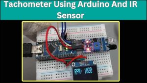
Physical connections
This is a physical connection image of this tachometer.

Program/Code:
#include <Wire.h>
#include <Adafruit_GFX.h>
#include <Adafruit_SSD1306.h>

#define OLED_RESET 4
Adafruit_SSD1306 display(OLED_RESET);

const int IR_PIN = 2;  // IR sensor input pin

volatile unsigned int counter = 0;  // Counter variable for revolutions
unsigned long previousMillis = 0;  // Variable to store previous time
unsigned int rpm = 0;  // Variable to store RPM value

void IRinterrupt() {
  counter++;
}

void setup() {
  pinMode(IR_PIN, INPUT_PULLUP);
  attachInterrupt(digitalPinToInterrupt(IR_PIN), IRinterrupt, FALLING);

  display.begin(SSD1306_SWITCHCAPVCC, 0x3C);
  display.display();
  delay(2000);
  display.clearDisplay();
  display.setTextSize(2);
  display.setTextColor(SSD1306_WHITE);
  display.setCursor(0, 0);
  display.println("TEG");
  display.display();
  delay(2000);
  display.clearDisplay();
  display.setTextSize(2);
  display.setTextColor(SSD1306_WHITE);
  display.setCursor(0, 0);
  display.println("Tachometer");
  display.display();
  delay(2000);
}

void loop() {
  unsigned long currentMillis = millis();

  if (currentMillis - previousMillis >= 1000) {
    detachInterrupt(digitalPinToInterrupt(IR_PIN));
    rpm = (counter / 2) * 60;  // Calculate RPM
    counter = 0;
    attachInterrupt(digitalPinToInterrupt(IR_PIN), IRinterrupt, FALLING);
    previousMillis = currentMillis;

    display.clearDisplay();
    display.setCursor(0, 0);
    display.print("RPM: ");
    display.println(rpm);
    display.display();
  }
}
Program explanation
Include Libraries:
#include <Wire.h>
#include <Adafruit_GFX.h>
#include <Adafruit_SSD1306.h>
These lines contain the libraries required for communication (Wire) and working with the Adafruit SSD1306 OLED display.
Define Constants and Initialize Variables:
#define OLED_RESET 4
Adafruit_SSD1306 display(OLED_RESET);
Here, a constant OLED_RESET is defined to specify the reset pin for the OLED display. The Adafruit_SSD1306 object called display is created to interact with the OLED screen.
const int IR_PIN = 2;  // IR sensor input pin
volatile unsigned int counter = 0;  // Counter variable for revolutions
unsigned long previousMillis = 0;  // Variable to store previous time
unsigned int rpm = 0;  // Variable to store RPM value
- IR_PIN is a variable that stores the pin number to which the IR sensor is connected.
- Counter is a volatile variable that counts the number of revolutions detected by the infrared sensor. It’s declared as volatile because it’s modified within an interrupt service routine.
- previousMillis is used to store the previous time for timing purposes.
- The variable rpm is used to store the determined RPM value.
Interrupt Service Routine (ISR):
void IRinterrupt() {
  counter++;
}
This is an interrupt service routine (ISR) that gets called whenever a falling edge is detected on the IR sensor. It increments the counter variable, which keeps track of the number of revolutions.
Setup Function:
void setup() {
  pinMode(IR_PIN, INPUT_PULLUP);
  attachInterrupt(digitalPinToInterrupt(IR_PIN), IRinterrupt, FALLING);

  display.begin(SSD1306_SWITCHCAPVCC, 0x3C);
  display.display();
  delay(2000);
  display.clearDisplay();
  display.setTextSize(2);
  display.setTextColor(SSD1306_WHITE);
  display.setCursor(0, 0);
  display.println("TEG");
  display.display();
  delay(2000);
  display.clearDisplay();
  display.setTextSize(2);
  display.setTextColor(SSD1306_WHITE);
  display.setCursor(0, 0);
  display.println("Tachometer");
  display.display();
  delay(2000);
}- The setup function uses a pull-up resistor to initialise the IR sensor pin as an input. It also attaches the IRinterrupt ISR to the falling edge of the IR sensor input pin.
- It then initializes and configures the OLED display, briefly displaying “TEG” and “Tachometer” messages.
Loop Function:
void loop() {
  unsigned long currentMillis = millis();

  if (currentMillis - previousMillis >= 1000) {
    detachInterrupt(digitalPinToInterrupt(IR_PIN));
    rpm = (counter / 2) * 60;  // Calculate RPM
    counter = 0;
    attachInterrupt(digitalPinToInterrupt(IR_PIN), IRinterrupt, FALLING);
    previousMillis = currentMillis;

    display.clearDisplay();
    display.setCursor(0, 0);
    display.print("RPM: ");
    display.println(rpm);
    display.display();
  }
}
- In the loop function, the code checks if at least 1 second has passed since the last RPM calculation using currentMillis – previousMillis >= 1000.
- If a second has passed, it detaches the interrupt temporarily to prevent further counts, calculates the RPM (assuming two counts per revolution), then reattaches the interrupt.
- The calculated RPM value is then displayed on the OLED display.
Conclusion
This project is made using an infrared (IR) sensor and an OLED display with Arduino nano board. It counts the revolutions of a rotating object with an infrared (IR) sensor, calculates the RPM (revolutions per minute), and displays the RPM value on an OLED screen.
This project shows how to use Arduino microcontrollers to monitor and display rotational speed, which can be used in a variety of fields such as automotive, robotics, and industrial machinery maintenance.
Hi.
Well done mate but to enhance your project. Look at the model aircraft sector. Measuring the speed of model glo plug engines is very important especially with multi engine aircraft. An accurate taco is not only important but very expensive. Glo engines can turn propellers at 40,000 rpm and more. Petrol engines at 9000 and sometimes more. Drive shaft speeds on model cars is also important.
If these speeds are within your taco’s limits then produce a neat looking unit in a neat case. This would be a desirable item as long as your price is reasonable.
Best of luck
Jeff.
Hi Jeff,
Thanks for your valuable insights! We’ll definitely consider your suggestions for enhancing our project. But this is just a prototype project for learning.
Very interesting. I always wanted to complete an rpm visual unit to determine the slot car speeds. I just did not have the time. I will try this in my spare time and test it. Thanks. Keep up the good work. Simple things can amaze a brilliant mind.
I’m glad you like this project. That’s great! Please give us an update when you start working on it, and if you encounter any problems, we’re here to help you out.
Hello, where(supplier) can I buy this parts i will like to try the same project of Tachometer Using Arduino And IR Sensor
Thanks
Hi,
You are from which part of the world?
Hello
I built the little project, the sketch uploaded nicely, the IR is responsive but cannot get anything on OLED. I replaced and double checked the easy wiring, I even exchanged breadboard to no avail. The Oled is good as I plugged it into another project and it worked. It must be in the coding. Any suggestion?
That’s odd. Are you using the same OLED display? If yes, to which pins your OLED is connected to? Can you double check.
Hey there, After following this tutorial and spending about a day trying to figure out what was going wrong as my output kept showing zero despite a wave function on a serial plotter showing the IR sensor was sending info, I discovered the error in Arduino Nano Documentation
Your tutorial shows and code the IR pin to D5
According to the Nano documentation, Interrupts are only detected on pins 2 and 3. I think you might have tried to update that in a code explanation section, but not anywhere else
When I switched pins and updated the code, everything worked as expected. Thanks!
Hi!
Thank you for pointing out the mistake. I’ve made the corrections everywhere else, except for the circuit diagram, which I’ll replace with the correct version soon.