Last updated on March 23rd, 2024 at 04:33 pm
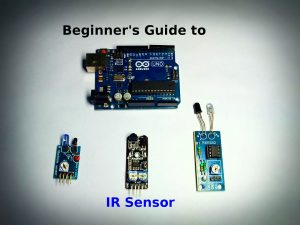
IR Sensor is a device that detects the object in front of it using IR or Infrared waves. It is also used to differentiate between black and white colors. Hence it is commonly used as the main sensor in a line follower robot.
Just like visible light, Infrared wave/light is part of the electromagnetic spectrum. But unlike sunlight/visible light, the human eye cannot see IR waves. Although it can be detected as heat.
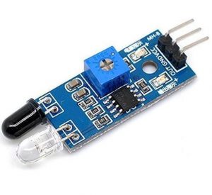
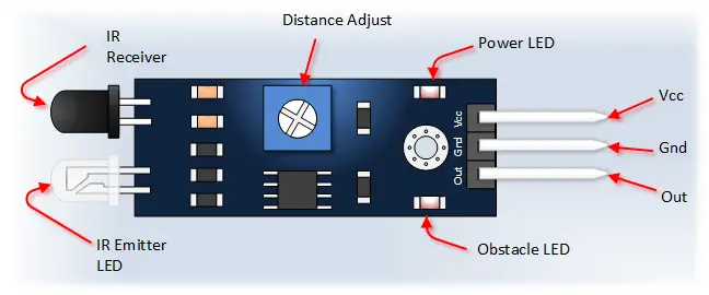
Every IR sensor has two main parts. IR Transmitter and IR Reciever. The work of an IR transmitter is to transmit infrared waves.
Whereas the work of the IR receiver is to receive these transmitted infrared waves. IR receiver constantly sends digital data in the form of 0 or 1 to the Vout pin of the sensor.
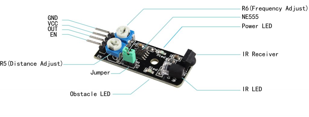
Note: The single potentiometer on most of the these sensors is used to set the sensitivity of the sensor or the distance up to which it detects the obstacle. So by rotating the potentiometer you can set the detection distance.
There are generally two LEDs on an infrared sensor, one is a power indicator and the other one is the output/obstacle indicator.
Table of Contents
Watch this video for a detailed explanation :
How does an IR Sensor work?
If there is an object in front of the sensor, the transmitted infrared waves from the IR transmitter reflect from that object and are received by the receiver. IR sensor gives 0 in this condition.
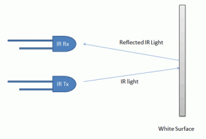
Similarly, if there is a white surface in front of the sensor, the IR waves are reflected back from the surface(the white surface does not absorb any light).
When there is no object in front, the transmitted infrared waves from the IR transmitter are not reflected and received by the IR receiver. The sensor gives 1 in this condition.
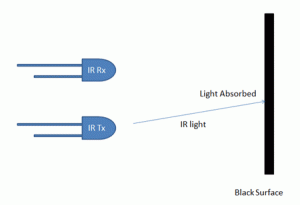
Similarly, if there is a black surface in front of the sensor, the IR waves are not reflected back from the surface(the black surface absorbs the light completely).
Different versions of IR sensor with pinout
Depending on the number of Pins and potentiometers, you may come across different versions of this sensor.
Based on the number of pins
1. With three pins

It has the following pinout: Power pin, Ground pin, and digital output pin. The digital output pin provides data in digital form i.e. 0(HIGH) or 1(HIGH).
- Ground
- 5 volt
- Vout (digital)
**IR receiver constantly sends digital data in the form of 0 or 1 to the Vout pin of the sensor.
2. With four pins(output type)
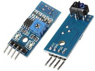
The sensor with four pins has the following pinout: Power pin, Ground pin, digital output, and analog output pin.
The analog output pin provides data in analog form i.e. between 0 volts and 5 volts(voltage at power pin)
3. With four pins(Enabling/disabling)
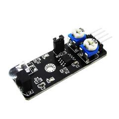
It has the following pinout: Power pin, Ground pin, digital output pin, and Enable pin.
The enable pin is used to enable/disable the IR sensor output.
- Ground
- 5 volt
- Vout (digital)
- Enable
**IR receiver constantly sends digital data in the form of 0 or 1 to the Vout pin of the sensor.
Image Source: Osoyoo.com
Based on the number of potentiometers
1. With a single potentiometer
The single potentiometer on most of the IR sensors is used to set the sensor’s sensitivity or the distance up to which it detects the obstacle. So by rotating the potentiometer, you can set the detection distance.
2. With two potentiometers
The second potentiometer is used to set the frequency of IR wave transmission.
Using IR sensor with Arduino
Now let’s interface the sensor with an Arduino UNO board. Gather these components:
- Arduino UNO
- IR sensor
- LED
Circuit diagram
Connect the components as shown below:
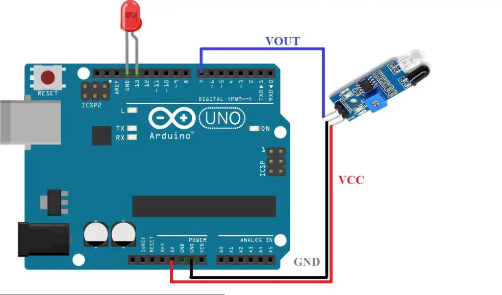
Connect the sensor’s VCC and GND pins to the Arduino’s 5V and GND pins, respectively. Connect the digital input pin of the sensor to digital pin 7 of UNO. The anode terminal(long leg) of the LED to pin 13 and the cathode terminal to the GND pin.
Program
Then upload this code to your Arduino board:
void setup()
{
  pinMode(7,INPUT);
  Serial.begin(9600);
  pinMode(13,OUTPUT);
}

void loop()
{

Serial.print("IRSensorip  ");
Serial.println(digitalRead(7));
if(digitalRead(7)==0)
{
  digitalWrite(13,HIGH);
  }
 else{
    digitalWrite(13,LOW);
    }
}
Hi
I want to build circuit with 2 relays , IR sensor and manual switch.
I have a problem with code sketch. Please send me email to trucker.poland @gmail com and let me know if are you able to help me or not .
Please answer as soon as possible.
Kind regards Greg
good project!!!!!
Hello,
I want to control 5 Led’s with 5 Ir detectors. How do I change the code to do this?
Thanks,
Gary
Hi Gary,
Do you want to control each LED from an individual sensor? Please provide more details so that we can help you out.
Ankit,
Yes I would like to control 5 or 6 LED’s with indivdual sr 505 IR sensors. The object is
to know the location of a model train in a tunnel.
Thanks,
Gary
Hi i want to control 2 9v dc motor and 2 ir sensor so like when my hand come near A sensor the A motor will work and can i also get the graph of all wires connected to the arduino
thanks
And also i have arduino uno r3
yes Ankit,
five or six SR501 infrad detectors controlling one Led each. I would like to use a arduino nano for this.
I am trying to tell the location of a model trains location in a tunnel.
Thank you for your quick response.
Gary
Hi Gary,
I have compiled this code for you as fast as I could. I haven’t tested it on the actual setup but this should work.
Controlling 5 different LEDs from 5 different IR Sensors:
You can use serial commands for real-time sensor data collection.
Let me know if this works or not.
Ankit,
I have had a quick test with two IR detectors (waiting for the mail to bring more) and it does
work. I am not sure what you mean by using serial commands?
I guess I would have to add the command: serial.begin (9600); but not sure were it goes.
This is my first attempt with arduino and I really appreciate the help.
Gary
Hi Gary,
Serial commands are used for serial communication between the Arduino board and Arduino software to receive data(such as from the sensor, keyboard)/send data. The data gets printed onto the Serial monitor of the Arduino software. You can also send data to the Arduino board using this serial monitor(using appropriate serial commands).
In your case, you can use the Serial monitor to print the real-time sensor readings(0 or 1) for sensor calibration and better control.
Serial.begin(9600) command initialize the communication hence goes into the void setup(). Any other serial command will not work if this is not used in void setup().
And I understand that learning Arduino can be very difficult if you are an absolute beginner.
You can learn Arduino programming from the internet/youtube as there are a ton of quality material available there. If you like, you can also go through this article on Arduino programming for beginners posted on our website:
Beginners guide to Arduino programming
Got it working with the serial. Thanks again for
the help Ankit.
Gary
Your welcome.
Happy to help 🙂
Ankit,
Yes, I would like to control 5 or 6 LED’s with individul SR505 IR Sensors. The object is to know
the location of a model train in a tunnel.
Thanks,
Gary
Thanks I will try it and get back to you
Thanks again Ankit.