Last updated on February 8th, 2025 at 11:21 am
Digispark is the Attiny85-based USB development board from Digistump. Due to the built-in USB connector, you can directly program the Attiny85 using Arduino IDE. This makes the use of ATtiny85 a lot easier since you don’t need a separate Arduino and a mess of jumper wires to program it.
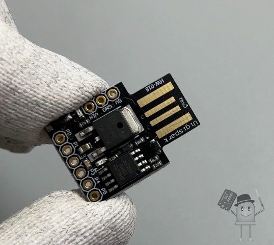
It has 8KB of flash memory, SRAM, and EEPROM of 512 bytes each, 6 digital pins, and 4 analog pins. Because of the onboard 5V regulator, you can supply it voltage between 7 to 35 volts. There is also a built-in LED connected to digital pin 1.
Here’s a table summarizing the specifications of the DigiSpark ATTiny85:
| Specification | Description |
|---|---|
| Microcontroller | ATtiny85 |
| Operating Voltage | 5V |
| Input Voltage | 5V (via USB) |
| Digital I/O Pins | 6 |
| PWM Pins | 3 (Pins: 0, 1, 4) |
| Analog Input Pins | 4 (Pins: 2, 3, 4, 5) |
| Flash Memory | 8 KB (of which 2 KB used by bootloader) |
| SRAM | 512 Bytes |
| EEPROM | 512 Bytes |
| Clock Speed | 16 MHz (via internal PLL) |
| Power Consumption | Approx. 5 mA at 5V |
| USB | USB 1.1 (with software USB support, no native USB hardware) |
| Dimensions | 26 mm x 18.8 mm (approximate board size) |
| Programming Interface | USB, using the Arduino IDE or other compatible software |
| Bootloader | Micronucleus |
Overview of Onboard Pins
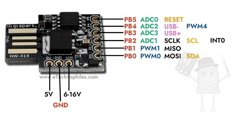
The onboard pins of the Digispark board are designed to offer a range of functionalities for various projects. Here’s a brief overview:
- Digital Pins: The board features 6 digital pins (P0 to P5).
- Analog Pins: There are 4 analog pins (P2 to P5) available for analog input.
- PWM Pins: 3 pins (P0, P1, and P4) support Pulse Width Modulation (PWM).
For a detailed pinout diagram, refer to the provided pinout chart.
Preparing the board
The board does not come with pre-soldered header pins, so you need to solder them separately. If you prefer using boards similar to the UNO, soldering female header pins would be suitable. However, for a more compact setup, I am opting for male header pins, which align with the mini or nano board approach.
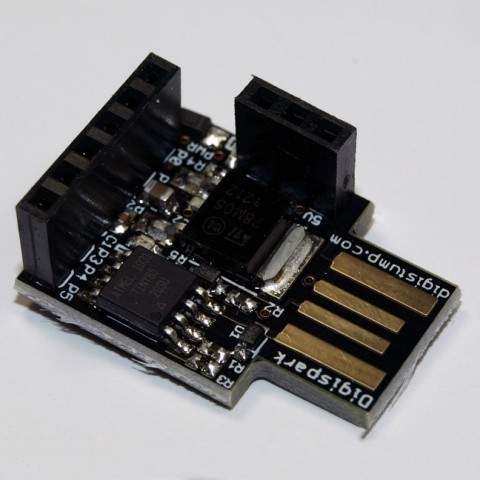
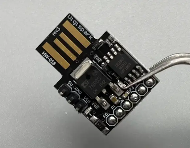
Using the Digispark on a breadboard can be challenging due to its design, which is not inherently breadboard-friendly. My approach involves placing the 6 digital pins on the breadboard and connecting the power pins using jumper wires.
Alternatively, you can directly connect the board to your laptop while it remains on the breadboard. Although this setup may not be aesthetically clean, it is functional.
Programming the Digispark ATtiny85 with Arduino 2.0
Now that your board is ready, lets see how to program it using Arduino 2.0 step by step:
Step 1: Install the Arduino IDE
Ensure you have the latest version of the Arduino IDE installed on your system. To install the Arduino IDE 2.3, visit the Arduino’s software page. After the installation is successful, open the IDE.
Step 2: Additional board manager
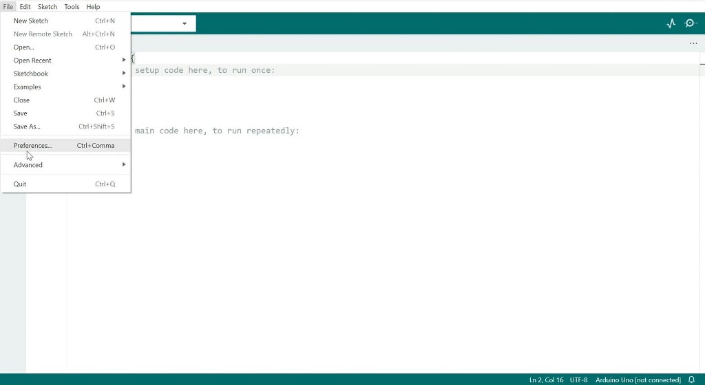
- On your dashboard navigate to
File → Preferences. - Paste the link given below into the “Additional Boards Manager URLs” field.
https://raw.githubusercontent.com/digistump/arduino-boards-index/master/package_digistump_index.json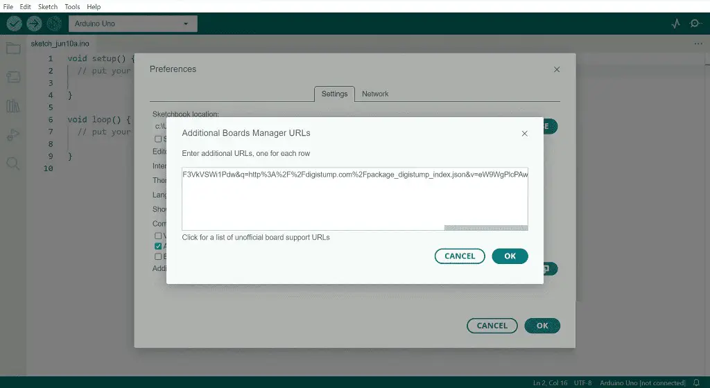
Step 3: Install Digistump AVR Board Package
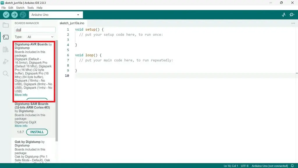
- Go to the Board Manager.
- Search for “Digistump” and install the “Digistump AVR boards” package.
Step 4: Upload a Blink Sketch
- To open the Blink sketch, go to File→Examples→Basics→Blink.
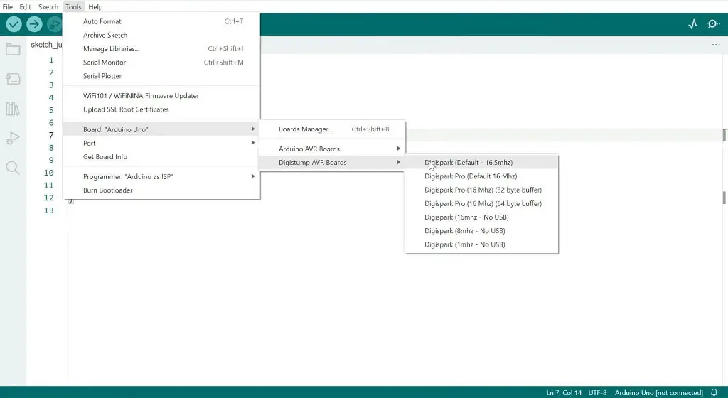
- In the Tools section, select Boards → Digistump AVR Boards and choose the “default-16.5 MHz” board.
- Don’t connect the board to your laptop yet. First, click on the upload button and wait for this message: “Plug in device now. Time out in 60 seconds”
- Once you get the message, insert the Digispark into the USB port. If everything works fine, you will see a successful upload message, and the built-in LED at pin 1 on the board will start blinking.
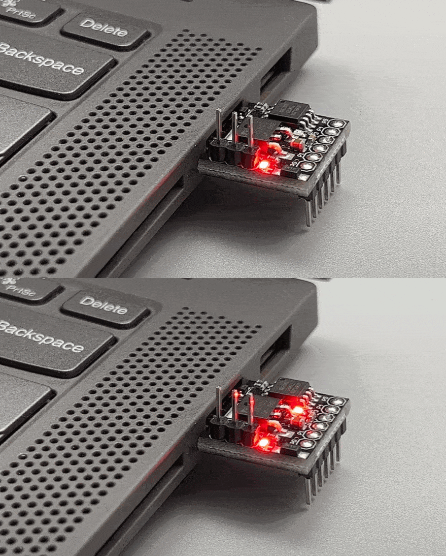
Finally, let’s put our Attiny85 board to use by utilizing its analog input and PWM functions. We’ll control the brightness of an LED using a potentiometer.
Example project- Using a potentiometer to control LED brightness
To demonstrate the board’s capabilities, we will control the brightness of an LED using a potentiometer. Here’s how to set it up:
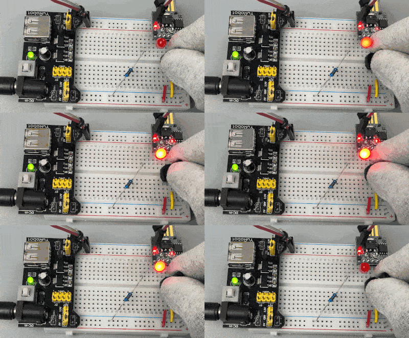
1. Connect components:
- Connect an LED to pin 1 through a 220-ohm resistor.
- Connect a potentiometer to pin 2, with its end terminals connected to 5V and ground, respectively.
2. Program the board:
- Upload the program given below to the board.
int led_Ext = 1;
int pot = A1;

void setup() {

pinMode(led_Ext, OUTPUT);

}

void loop() {

int pot_Value = analogRead(pot);
pot_Value = map(pot_Value,0,1023,0,255);
analogWrite(led_Ext,pot_Value);
delay(100);

}
3. Adjust LED brightness:
- Power the board, and you will be able to adjust the LED brightness by rotating the potentiometer.
With these steps, you are now equipped to explore more projects using the Attiny85 board.
Forget these now. DigiStump (from whence we get all our support for these) has gone out of business recently so you’re on your own getting these things to work.
Oh, and they’ll never truly work as a USB client.
Thank you, Mr. Vikas, for the information. I’ve tried the “digistump” link you provided, and it works 100%. Thank you very much for your contributions, and God bless you for taking a few minutes of your life to educate us. Best regards.
I am glad to be of help 🙂