In this blog post, you will learn how to make your own servo tester step by step. This controller can test 6 servo motors independently. The overall cost of this Arduino project is around $5 if you make it on a breadboard or a zero PCB.

Currently, I am working on a 3D-printed robotic arm that needs several servos. To control them, I needed a servo motor controller with at least 6 channels. While browsing Amazon, I found one with great reviews, but it was too costly.
So, I decided to build one myself using an Arduino Nano and some spare parts I had lying around.
Watch the video tutorial below:
Table of Contents
Components Required
You need the following components to make this project
- Arduino Nano
- Potentiometer(10K ohm) X 6
- Push button X 6
- Servo motors
- PCB(optional)
Circuit Diagram

If you are using a Nano in your project, you need to make some changes to the circuit connections as given in the table below.
| Component | Nano | UNO |
|---|---|---|
| Servo Motor | D3,D5,D6,D9,D10,D11 | D3,D5,D6,D9,D10,D11 |
| Potentiometer(Wiper terminal) | A1,A2,A3,A4,A5,A6 | A0, A1,A2,A3,A4,A5 |
| Potentiometer(one end) | +5V | +5V |
| Potentiometer(other end) | GND | GND |
| Push button(one end) | D2,D4,D7,D8,D12,A0 | D2,D4,D7,D8,D12,D13 |
| Push button(other end) | GND | GND |
Note: The last button is connected to pin 13 on the Uno in Tinkercad, but in the actual circuit on the Nano, it will be connected to pin A0. Why? Because there is an issue with Nano’s pin 13 when you use it as a digital input with input pullup. If you are going to use UNO, there’s no need to make any changes. Just follow the circuit diagram.
If you’re eager to try this circuit right now, you can just copy my design from here in Tinkercad and start right away. You can also simulate the circuit below, on this page itself.
Servo controller circuit on a breadboard
You can build this circuit on a breadboard as well. However, it can be a bit challenging if you are a beginner as there are many connections to be done.
I built this on a breadboard for two servo motors(see the image below).

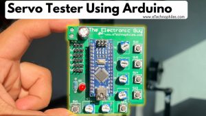
PCB design
Confident with the program and circuit, it was time to make it compact. For this, I designed the PCB in CircuitMaker. After finalizing the design, I ordered the PCBs from a local manufacturer.
And in just 5 days, the parcel arrived at my doorstep. The PCB quality is decent: the silkscreen, solder mask, everything.

How to use this Servo Tester?
There are two modes to control each servo motor:
- “Manual/pot.” mode using the potentiometer, where based on its rotation the servo position changes.
- “Auto/0 degree” mode in which the servo resets to its original position when the push button is pressed, which is 0 degrees by the way.
When the circuit is powered, the tester is by default set to manual/potentiometer mode. If you press the button, the servo motor resets to zero, making the potentiometer inactive. Press the button again, and manual mode is back in action.
Program
/*
***********************6 Channel Servo Motor Tester**************************
*
* Created on: May 27, 2021
* Author: Ankit Negi
*
* Youtube: www.youtube.com/theelectronicguy
* Website: www.eTechnophiles.com
*/


/* When the circuit is powered, the servo is by default in manual/potentiometer mode. As soon
as the button is pressed, the 'Auto/ 0 degrees' mode is set and nothing happens when the pot is rotated.
On pressing the button again, the mode changes and now motor can be controlled using the pot*/

/*Use this code while using Arduino Nano. For UNO, make the changes as explained in the circuit diagram section*/

#include <Servo.h> // servo library

Servo myservoA;
Servo myservoB;  // create servo object to control a servo
Servo myservoC;
Servo myservoD;
Servo myservoE;
Servo myservoF;

int potpinA = A1;
int potpinB = A2;  // analog pins for potentiometers
int potpinC = A3;
int potpinD = A4;
int potpinE = A5;
int potpinF = A6;

int valA;  // variable to read the value from the analog pin
int valB;
int valC;
int valD;
int valE;
int valF;

#define buttonA A0 // Pins connected to buttons
#define buttonB 12
#define buttonC 8
#define buttonD 7
#define buttonE 4
#define buttonF 2

bool button_stateA = false; // variable storing the current state of the button
bool button_stateB = false;
bool button_stateC = false;
bool button_stateD = false;
bool button_stateE = false;
bool button_stateF = false;

void setup() {
  myservoA.attach(3);// pins connected to Servo motors
  myservoB.attach(5);
  myservoC.attach(6);
  myservoD.attach(9);
  myservoE.attach(10);
  myservoF.attach(11);

  int buttons[] = { A0, 12, 8, 7, 4, 2 }; // set input pullup on button pins
  for (int i : buttons) {
    pinMode(i, INPUT_PULLUP);
  }
}

void loop() {
  read_Button();// function to read current state of the button
  val_Read(); // function to read the analog pins/pots
  val_Map(); // function to map the analog input to servo position(0 to 180 degrees)
  test_Servo();// sets the servo position according to the mapped value
  delay(15);  // waits for the servo to get there
}

void read_Button() {
  if (digitalRead(buttonA) == 0) {// if buttonA is pressed
    button_stateA = !button_stateA;// change the button state
  }
  if (digitalRead(buttonB) == 0) {
    button_stateB = !button_stateB;
  }
  if (digitalRead(buttonC) == 0) {
    button_stateC = !button_stateC;
  }
  if (digitalRead(buttonD) == 0) {
    button_stateD = !button_stateD;
  }
  if (digitalRead(buttonE) == 0) {
    button_stateE = !button_stateE;
  }
  if (digitalRead(buttonF) == 0) {
    button_stateF = !button_stateF;
  }
  delay(150);
}

void val_Read() {
  valA = analogRead(potpinA);
  valB = analogRead(potpinB);
  valC = analogRead(potpinC);
  valD = analogRead(potpinD);
  valE = analogRead(potpinE);
  valF = analogRead(potpinF);
}

void val_Map() {
  valA = map(valA, 0, 1023, 0, 180);
  valB = map(valB, 0, 1023, 0, 180);
  valC = map(valC, 0, 1023, 0, 180);
  valD = map(valD, 0, 1023, 0, 180);
  valE = map(valE, 0, 1023, 0, 180);
  valF = map(valF, 0, 1023, 0, 180);
}

void test_Servo() {
  switch (button_stateA) {
    case 0:// 0 means the button state is false
      myservoA.write(valA);// if the button is false, pass the mapped value
      break;
    case 1:// 1 means the button state is True
      myservoA.write(0);//if the button state is true, set the servo to 0 degrees
      break;
  }

  switch (button_stateB) {
    case 0:
      myservoB.write(valB);
      break;
    case 1:
      myservoB.write(0);
      break;
  }

  switch (button_stateC) {
    case 0:
      myservoC.write(valC);
      break;
    case 1:
      myservoC.write(0);
      break;
  }

  switch (button_stateD) {
    case 0:
      myservoD.write(valD);
      break;
    case 1:
      myservoD.write(0);
      break;
  }

  switch (button_stateE) {
    case 0:
      myservoE.write(valE);
      break;
    case 1:
      myservoE.write(0);
      break;
  }

  switch (button_stateF) {
    case 0:
      myservoF.write(valF);
      break;
    case 1:
      myservoF.write(0);
      break;
  }
}
The Arduino program for this servo tester is given below. Just copy the code and paste it into your IDE. You can also download the code from here.
Code explanation
Here’s a detailed explanation of the code for the 6-channel servo tester
1. Including the Servo library
#include <Servo.h> // servo libraryThe code starts by including the Servo library, which is essential for controlling the servo motors. This library provides easy-to-use functions to control the position of standard hobby servo motors.
2. Creating Servo objects
Servo myservoA;
Servo myservoB;
Servo myservoC;
Servo myservoD;
Servo myservoE;
Servo myservoF;
Here, we create six servo objects (myservoA to myservoF) to control six different servo motors. Each object will be linked to a specific pin on the Arduino Nano, allowing us to send control signals to the corresponding servo.
3. Defining Input pins for potentiometers and buttons
int potpinA = A1; // analog pins for potentiometers
...
int potpinF = A6;

#define buttonA A0 // Pins connected to buttons
...
#define buttonF 2
This section defines the pins connected to the potentiometers (potpinA to potpinF) and the buttons (buttonA to buttonF). The potentiometers provide analog input to control the servo positions, while the buttons are used to switch between “Manual Mode” and “Auto Mode.”
4. Defining variables for button states and potentiometer Values
bool button_stateA = false; // variables storing the current state of the buttons
...
int valF;  // variables to read the value from the analog pins
We declare boolean variables (button_stateA to button_stateF) to store the current state of each button (pressed or not). We also define integer variables (valA to valF) to store the analog values read from the potentiometers.
5. Setup() function
void setup() {
  myservoA.attach(3); // pins connected to Servo motors
  ...
  myservoF.attach(11);

  int buttons[] = { A0, 12, 8, 7, 4, 2 }; // set input pullup on button pins
  for (int i : buttons) {
    pinMode(i, INPUT_PULLUP);
  }
}- Servo Attachments: The attach() method links each servo object to a specific pin on the Arduino (3, 5, 6, 9, 10, 11).
- Input Pull-Up for Buttons: The code uses an array buttons[] to set the pins connected to the buttons as input with an internal pull-up resistor using pinMode(). The INPUT_PULLUP mode helps avoid floating pin states by ensuring a defined voltage level when the button is not pressed.
6. The main loop
void loop() {
  read_Button(); // function to read current state of the button
  val_Read();    // function to read the analog pins/pots
  val_Map();     // function to map the analog input to servo position (0 to 180 degrees)
  test_Servo();  // sets the servo position according to the mapped value
  delay(15);     // waits for the servo to get there
}
The loop() function repeatedly calls four sub-functions:
- read_Button(): Checks the state of each button and toggles its state if pressed.
- val_Read(): Reads the analog values from the potentiometers.
- val_Map(): Maps the potentiometer values (0-1023) to the servo range (0-180 degrees).
- test_Servo(): Sets the servo positions based on the mapped values and button states.
7. Reading button Sstates with read_Button() function
void read_Button() {
  if (digitalRead(buttonA) == 0) { // if buttonA is pressed
    button_stateA = !button_stateA; // toggle the button state
  }
  ...
  delay(150);
}- This function reads the state of each button. If a button is pressed (digitalRead() == 0), it toggles its corresponding state variable(button_stateX).
- A delay of 150 milliseconds is added to debounce the button presses, ensuring that a single press is registered only once.
8. Reading potentiometer values with val_Read()
void val_Read() {
  valA = analogRead(potpinA);
  ...
  valF = analogRead(potpinF);
}
This function reads the analog values from each potentiometer and stores them in corresponding variables (valA to valF). These values range from 0 to 1023.
9. Mapping potentiometer values with val_Map() function
void val_Map() {
  valA = map(valA, 0, 1023, 0, 180);
  ...
  valF = map(valF, 0, 1023, 0, 180);
}- The map() function converts the raw potentiometer values (0-1023) to a range suitable for the servos (0-180 degrees). This is necessary because servos operate within a 0 to 180-degree range.
10. Controlling servos with test_Servo() function
void test_Servo() {
  switch (button_stateA) {
    case 0: // Manual Mode
      myservoA.write(valA); // set servo to potentiometer value
      break;
    case 1: // Auto Mode
      myservoA.write(0); // reset servo to 0 degrees
      break;
  }
  ...
}- This function checks the state of each button and sets the servo position accordingly.
- If the button state is 0 (Manual Mode), the servo position is set based on the potentiometer’s mapped value.
- If the button state is 1 (Auto Mode), the servo is reset to the 0-degree position.