Last updated on March 19th, 2024 at 05:58 pm
Breadboards are used for testing and prototyping electronic circuits without the need for soldering or making permanent connections. It makes the process of testing and debugging a circuit easy, making it an ideal tool for professionals and beginners. Let’s start with their history first.
Table of Contents
Why is a breadboard called so? History
The term “breadboard” originated from the early days of electronics when people used to prototype their circuits on wooden cutting boards used for slicing bread, hence the name “breadboard”.
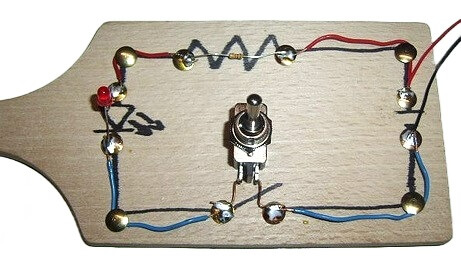
**Image source: Real breadboard for prototyping a circuit
Since then, the name breadboard has become popular. As you can see in the picture above: nails are hammered into a wooden board, wires wrapped around them, and components glued to the board. Back then, components were big, and circuits were not that complex, so it worked out.
Later, when the circuits’ complexity increased, engineers used a method called wire wrapping.
Wire wrapping method
In the Wire wrapping method, a board with holes is used. Components are then inserted in these holes from one side. Then wires are wrapped around the pins of the components to make connections. In complex circuits, one has to wrap many wires on the same pin, and undoing them is really annoying and challenging.
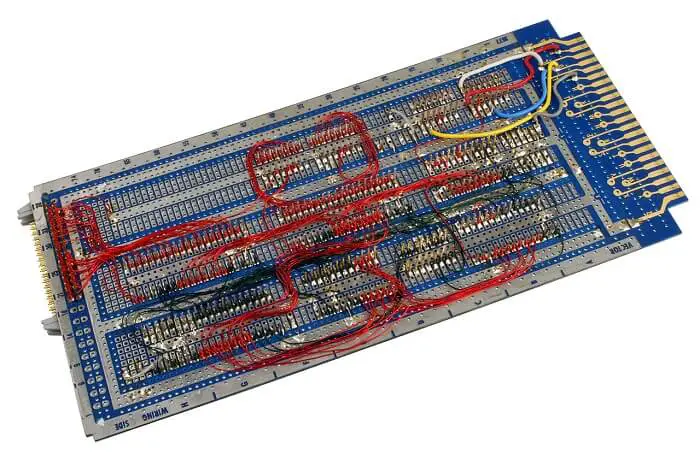
This method worked well with digital components, but with analog components, it created problems like cross talk, electromagnetic interference, and impedance.
Different methods were used in the wire wrapping technique: Manual wire wrap, semiautomated wire wrap, and automated wire wrapping. This method is no longer in use due to its drawbacks and inefficiency. But many people still do it as a hobby.
Introduction to breadboard
Modern breadboard was Introduced in the 1970s by Ronald J Portugal. It was named “solder-less breadboard” and later shortened to “Breadboard”.
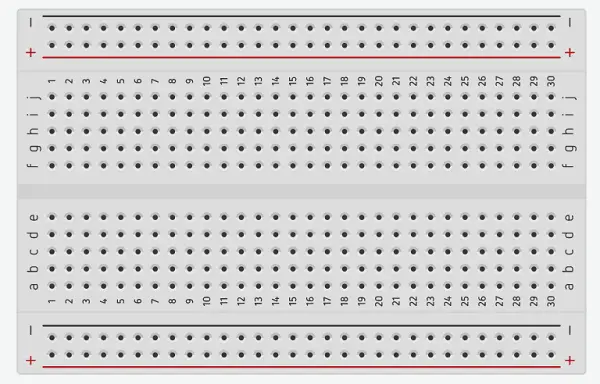
Modern breadboards are rectangular in shape with holes arranged in a grid pattern. The holes are connected to metal strips that run beneath the board. These strips are used to make electrical connections between different components.
At the backside of a breadboard, there is a yellow waxy paper with sticky foam. That foam on the back side is a double-sided tape used to stick the board onto something. If you peel off the foam and yellow paper, you can see metallic strips underneath. These are spaced at a pitch of 2.54 mm.
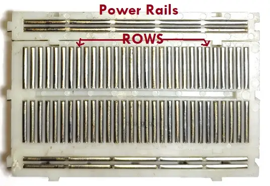
Each metal strip has five metal sockets(claw shape)designed in such a way that the legs of the components can be properly inserted. The vertical or terminal strips with five sockets run parallel to each other. Whereas the horizontal strips called power rails have no break in between. Each metal socket is spaced at a pitch of 2.54 mm.
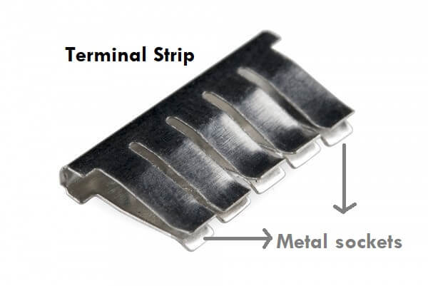
Note: When a component is inserted halfway into a hole, the metal socket underneath stretches. Upon full insertion, the socket locks the pin in its place, making a stable connection.
Parts of a breadboard
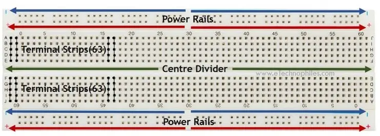
Power rails(+ and -): Used to create +ve and -ve nodes for the circuit. Suppose you want to power your circuit with a 9 V battery. The +ve and -ve terminals of the battery are connected to the +ve(Red) and -ve(Blue/Black) power rails, respectively. Due to this, every hole in the + power rail gets 5 V. And now you have multiple 5V nodes. Similarly, for the – power rail, you have multiple ground nodes.
There are four horizontal stripes in total; a pair of + and – power rails on both sides. In order to fully utilize a solderless board while making projects, you may need power rails on both sides. So to power each rail type, you can either power them separately or connect them using a jumper wire.
Note: If your breadboard has a split-power rail, you can connect jumper wires(on both sides) to bridge the split and convert it into a full-power rail board.
Terminal Strips: The components are inserted in these strips. If you insert a component pin in any of the strips, that pin will be internally connected to the whole strip, and you will get 4 more nodes(holes). Now you can use any of those holes to connect that pin to other parts of the circuit.
Center divider: Also known as DIP support, divides the breadboard into two halves. The parallel terminal strips on both sides create a perfect space for inserting DIP ICs into the breadboard.
In a half-size breadboard, the holes are fewer in number as compared to the full-size breadboard. In the case of the mini breadboard, there are only two rows and no power rails.
Why are there numbers and letters?
A full-size breadboard has 10 columns(a to j) and 30 rows(1 to 30) with a divider in between. Small-size board has 63 rows(1 to 63), and the mini-size one has no such markings.
These labels help you to track the connections that you are making. Now they may not be useful in simple projects, but in complex projects, they can surely save you a lot of time.
For example- Given below is an adjustable voltage regulator project. The middle terminal or wiper terminal of the potentiometer is connected to hole A8.
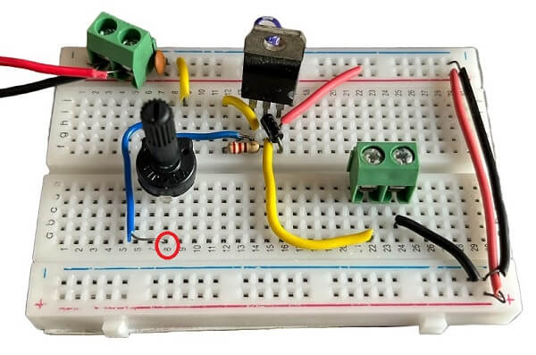
Note: Some boards do not have any such markings.
Types of Breadboard
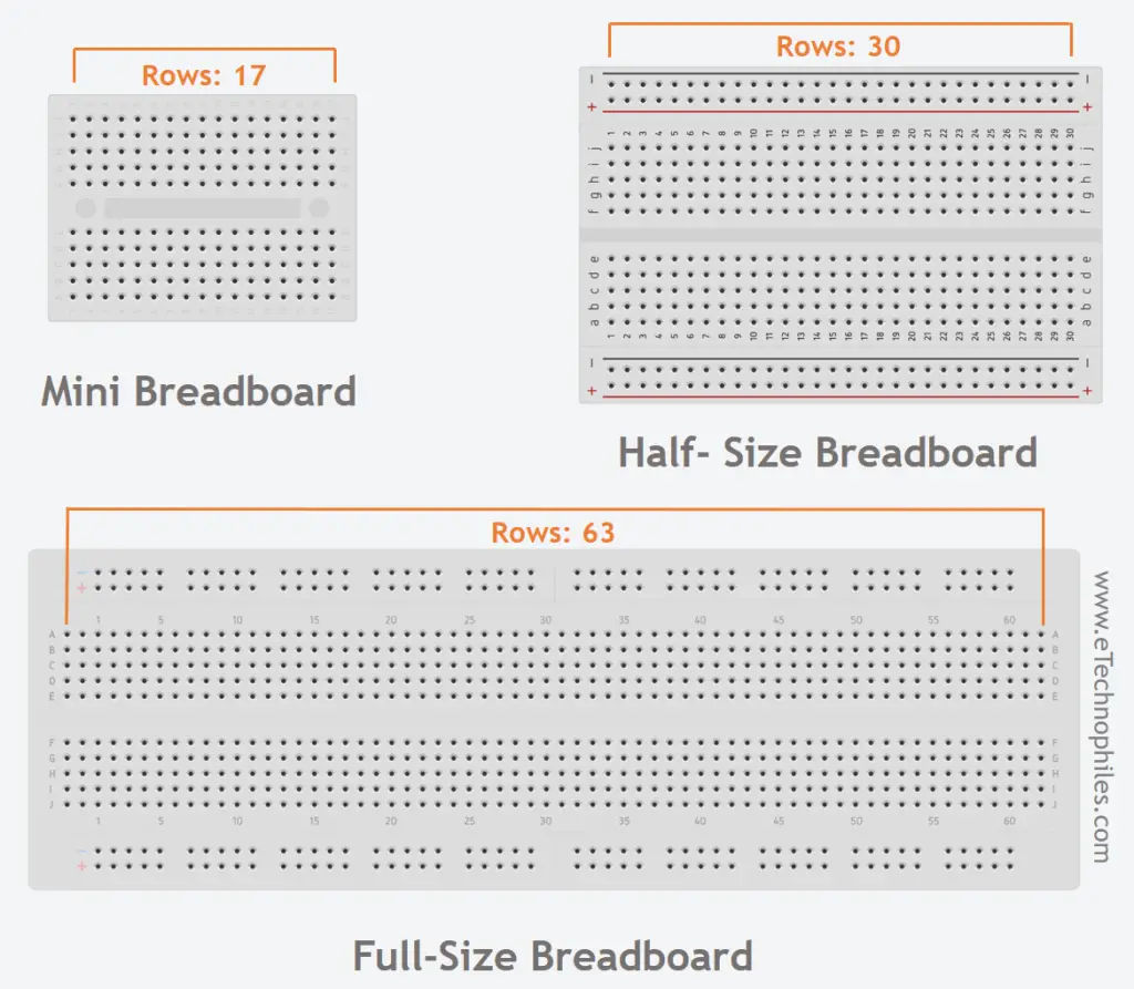
Breadboard is categorized based on size; the most common one has 840 holes with a size of 7 x 2.9 x 0.6 inches.
The Half-size board comes with 400 holes and a size of 3.2 x 2.4 inches.
The mini solderless board comes with 170 holes with a size of 1.8 x 1.3 inches.
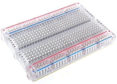
Although white is a common color, these come in various other colors as well, such as black, red, and more. Transparent breadboards are also widely used since they look neat.
Breadboard with Binding posts
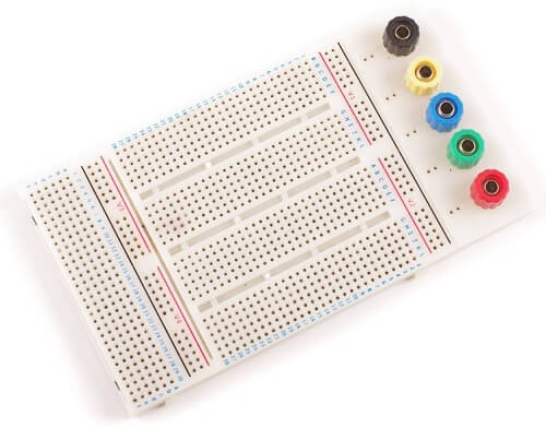
Some variants come with binding posts. These posts make it easy to connect various external power sources to the board. Please note that these posts are not internally connected to the breadboard anywhere. So you still have to connect the power rails to the binding posts.
How to use a breadboard?
Step 1: Gather components
You need the following components for this project:
- LED
- 220-ohm resistor
- Push button
- Breadboard
- 9V battery
- Battery clip with a connector
- Jumper wires
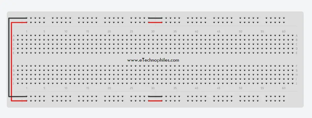
Step 2: Power rails
Connect the +ve and -ve power rails, as shown below.
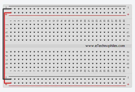
If you have a full-size breadboard with a split power rail, connect the rails using wires as shown below.
Step 3: Place the components
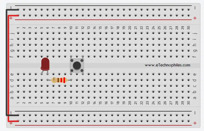
- Place the breadboard with horizontal rows (a-j) and vertical columns (1-30 or more) facing you.
- Insert the LED’s anode (longer leg) in hole E5 and the cathode (shorter leg) in hole E6.
- Connect one end of the 220-ohm resistor to hole D6 and the other end to hole D10.
- Place the push button across the center divider of the board, with two legs on the left side (e.g., E10 and E13), and the other two legs on the right side (e.g., F10 and F13).
Step 4: Connect the components using jumper wires
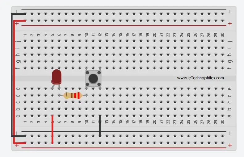
- Connect A5 (Anode of the LED) to the positive supply rail.
- Connect A12 (the other leg of the push button) to the negative power supply rail.
Step 5: Connect the battery
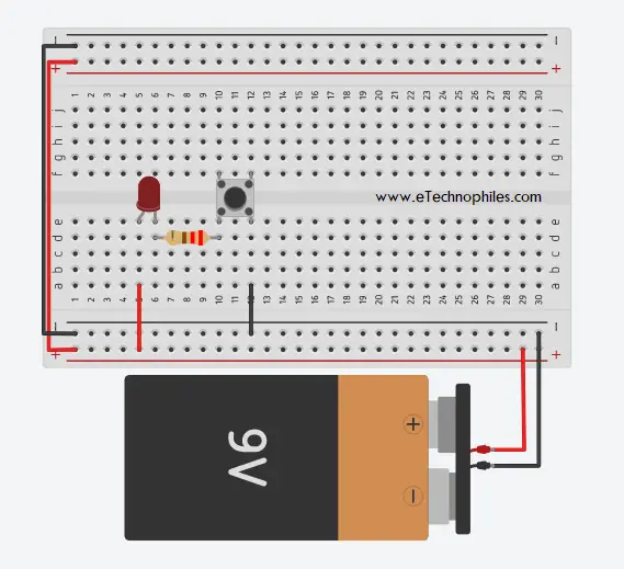
- Attach a battery clip to the 9V battery (red wire for positive, black wire for negative).
- Insert the red wire from the battery clip into any positive power supply rail hole.
- Insert the black wire from the battery clip into any negative power supply rail hole.
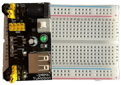
We have used a 9V battery in this example. You can also use a bench power supply or a breadboard power supply which has a USB plug and can provide both 5V and 3.3V.
Step 6: Test the circuit
- Press the push button to test. The LED should light up when pressed and turn off when released.
Note: Ensure all the connections are secure and there are no loose wires or components.
Why should you use a breadboard(advantages)
Breadboards are cheap and widely available and it makes prototyping effortless. It may look tedious on the first few tries but with practice, you can learn how to make circuits more efficiently.
There are many advantages of using them.
- Easy to prototype simple and complicated circuits.
- Quick to check components before using them in actual electronics projects.
- No need to learn complex CAD software to test out initial circuits.
- Solderless connections make it reusable.
Disadvantages
- It is temporary.
- It is heavier.
- It shows poor performance for high-speed designs.
- SMD components cannot be tested on them.
- High parasitic inductance, resistance, and capacitance between two adjacent rows.
Conclusion
Breadboards are an essential tool for anyone who wants to learn about electronics prototyping. They are easy to use, affordable, and allow you to quickly build and test circuits without the need for soldering or any permanent connections.
If you’re just starting in electronics, it should be one of the first tools you acquire. With a little bit of practice, you can build more complex circuits and take your electronics skills to the next level. There are a few online simulation tools for practicing with breadboard and various other components one such online tool is Tinkercad.
