Last updated on April 3rd, 2024 at 05:34 pm
A voltage regulator is an electronic circuit that maintains a constant voltage level. This is often used to protect electronic equipment from power fluctuations and to maintain a consistent voltage level for various devices. In this article, we will discuss the importance and circuits of different regulator types.
Table of Contents
Need for voltage regulation
Electronic devices are designed to use DC supply. These devices are modeled to have a predefined power rating i.e. current and voltage. The DC supply can be provided using a battery or cell, which can be expensive. Instead, AC supply is converted into DC supply.
The current utilization is dynamic and dependent on the load, which affects the output voltage or the power rating. Hence, voltage regulation is required for the proper functioning of the devices for maintaining the power rating in any conditions.
What is a voltage regulator?
It is an integrated circuit (IC) that maintains a stabilized output voltage within a pre-accepted value. And this stable output voltage is then fed to the output device/equipment. This output voltage is the maximum value that can be sustained by that equipment without getting damaged.

The voltage regulator may use a simple feed-forward design or may include negative feedback. The design can consist of either an electromechanical mechanism or electronic components.
- Electronic voltage regulators are placed in devices such as computer power supplies where they regulate the DC voltages used by the processor or the other elements.
- In an electric power distribution system, they may be installed at a substation or along the distribution lines so that they get steady voltage irrespective of how much power is consumed from the line.
How a DC voltage is achieved?
Voltage regulation gives a fixed DC output voltage independent of the AC line input voltage variation, load current, and temperature. The block diagram shows how the AC supply is converted to constant DC:

Transformer: Step up / step down AC voltage provided by the desired action of the magnetic field.
Rectifier: Converts AC input voltage into pulsating DC voltage.
Filter: reduce fluctuations in the rectified output voltage or ripples. This provides a constant dc voltage.
Voltage Regulator: gives a fixed voltage value to the load, regardless of the input voltage value.
How does a voltage regulator work?
To understand its working, consider the circuit shown in the figure below. A voltage regulator circuit is installed between the supply voltage (input) and the electrical load (output).
Due to some disturbances, the input voltage may either increase or decrease from its rated value. The voltage regulator acts accordingly to nullify the effect. Consider these two cases:

Case 1: If the magnitude of output voltage exceeds the rated voltage
In this case, the control elements inside the voltage regulator increase the voltage drop across it, thus reducing the output voltage magnitude to the nominal rating.
Case 2: If the magnitude of output voltage drops below the rated voltage
In this case, the voltage drop across the voltage regulator gets reduced, hence the rated voltage is again obtained at the output terminal.
In this way, a voltage regulator always maintains the rated voltage across the output terminals.
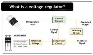
Parts of a voltage regulator
Generally, its circuit consists of three parts:
- The control circuit (pass element): It checks the magnitude of unregulated voltage and passes regulated voltage as output.
- The sampling circuit: It samples a proportion of the output voltage and compares it to the reference voltage.
- The comparator circuit: It compares the feedback signal with a fixed reference voltage and generates a control signal for the control element.
Types
There are two types of voltage regulators:
- Linear
- Switching
Note: While discussing the components of a voltage regulator and its purpose, we will consider the transistor as the pass element in the voltage regulator.
Linear voltage regulator
When a transistor operates in the active region (or acts as a switch) to control the output voltage, then this type of regulator is known as a linear voltage regulator.
Types of linear voltage regulators (based on the nature of output voltage)
The linear voltage regulators are further categorized into four types, they are:
- Fixed Output
- Adjustable
- Tracking
- Floating
Fixed
A fixed voltage regulator produces a fixed DC output voltage, which is either positive or negative.
Positive fixed voltage regulator: IC 78xx series
Negative fixed voltage regulators: IC 79xx series
The following points must be noted while working with the 78xx and 79xx series:
- “xx” represents the magnitude of voltage that a voltage regulator IC produces
- Both series have 3 pins and the 3rd pin is used to collect the output.
- The first and second pins of 78xx ICs are used for connecting the input and ground respectively.
- The first and second pins of 79xx ICs are used for connecting the ground and input respectively.
Adjustable
An adjustable voltage regulator produces a DC output voltage, that can be tuned to any other value of a certain voltage range. It can be either positive or negative.
Positive adjustable voltage regulator: LM317 voltage regulator IC
Negative adjustable voltage regulator: LM337 voltage regulator IC
Types of linear voltage regulators (based on the location of pass element)
A linear voltage regulator uses a closed feedback loop to pass a bias element to get a fixed voltage across its output terminals. Based on how the load is connected to the pass element, it is further classified into:
- Series
- Shunt
Series

In this regulator, the control element is connected in series with the load. By changing the resistance of the series element, the voltage drop across it can be changed. Output load voltage remains constant depending on the comparator and the controller.
In series voltage regulators, no current is diverted away from the load, hence they are more efficient than the shunt ones. To understand the working of the series regulator in detail, consider two cases:
Case 1: If the output voltage increases
In this case, the comparator circuit provides a control signal to the series control element to reduce their magnitude of output voltage, thus maintaining a fixed output voltage.
Case 2: If the output voltage decreases
In this case, the comparator circuit provides a control signal to the series control element to increase their magnitude of output voltage, again maintaining a fixed output voltage.
Shunt

The shunt voltage consists of a variable resistance that provides a path to the current from the supply voltage to the ground. As a part of the current is diverted away from the load, it is less efficient than the series regulator. The figure above shows a shunt voltage regulator that contains a control element, a comparator, and a sampling circuit.
If the output voltage tends to change due to the change in load, then the sampling circuit provides a feedback signal to the comparator circuit. Thus the comparator provides a control signal to vary the magnitude of the current shunted away from the load. Hence it keeps the output voltage regulated.
Advantages of linear voltage regulator
A linear voltage regulator offers the following advantages:
- They have a simple design.
- They have a fast response time, i.e., they respond quickly to changes in load voltage.
- The output voltage contains fewer ripples.
- They have a better noise rejection ratio, i.e., low electromagnetic interference and less noise
Disadvantages of linear voltage regulator
- Their efficiency is low.
- Although they have a simple design, the space requirement is large.
- The output voltage cannot be increased beyond the rated voltage, i.e., only step-down (buck) operation is possible.
- A heat sink is sometimes required due to considerable heat generation.
- They are economical as compared to switching voltage regulators.
Switching voltage regulator
When the transistor switches between the cut-off state and saturation state, then the regulator is called as switching voltage regulator.
This regulator also has a feedback mechanism to control the amount of charge transferred to the load. It is set as the duty cycle of the switch, which controls the output voltage at a constant value.
In the figure below, the transistor acts as the switching element that connects and disconnects the input power to the load. It can be a BJT or MOSFET and it will operate in the saturation or cut-off region.

Switching regulators are efficient because no power is dissipated as the series element is either fully conducting or switched off. Switching regulators can generate higher output voltages than the input voltage or of opposite polarity.
Types of switching voltage regulators (based on the circuit design)
Based on the circuit design, we can classify switching voltage regulators into two types:
- Non-isolated converters
- Isolated converters
The non-isolated converters can be further classified into three types:
- Step down voltage regulator (Buck converter)
- Step-Up voltage regulator (Boost converter)
- Buck / Boost converter
While the isolated converters can be classified into two types:
- Fly back converters
- Forward converters
Advantages of switching voltage regulators
- Their efficiency is very high.
- The size and weight of the converter is very low.
- Boost or buck or inverting or buck/boost operation is possible
- They generate less heat as compared to linear voltage regulators.
Disadvantages of switching voltage regulators
- The transient recovery time is more.
- The noise production is higher.
- They are costlier as compared to linear voltage regulators.
- They have a complex design, i.e., more external parts are required.
Application of voltage regulators
They are used in most electrical and electronic devices. Some of them are listed below:
- Mobile charger: AC input signal is fed to the adapter, whereas regulated DC signal is produced as output.
- Television, computer, and all class of electronic devices use a voltage regulator to get the desired output voltage.
- ICs and other small electronic circuits: To protect from damage due to the slightest fluctuation in voltage signal.
- Power generation system: In windmills, electricity is generated according to the wind speed. So, a regulator is required for generating a constant output signal.
FAQs
What does a voltage regulator do?
A voltage regulator is a device or circuit that maintains a steady output voltage regardless of changes in input voltage or load conditions.
Which diode is used as a voltage regulator?
The Zener diode is commonly used as a voltage regulator. When operated in its reverse-biased breakdown region, it maintains a nearly constant voltage across its terminals, making it suitable for voltage regulation applications.
Informative content👍🏼