Last updated on January 6th, 2026 at 11:25 am
A multimeter is undoubtedly the most popular electronics/electrical tool and is used by technicians, engineers, and people from non-technical backgrounds alike. A multimeter is used to check the open circuits, measure current, resistance, and voltage, and for debugging the circuits.
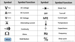
Hence, you can perform many functions and measure various electrical quantities using a multimeter. Each function is represented by a unique symbol on the multimeter. So to use a multimeter properly, one must be aware of all these symbols and their usage. In this article, you will learn about multimeter symbols and their function.

Table of Contents
Multimeter parts
Every multimeter has the following parts:

- Display– displays the value of the measured quantity.
- Knob/Rotary dial- Selects multimeter functions.
- Probes– are the point of contact for measurement.
- Ports– Connects probe to the inside circuitry of a multimeter.
- Buttons– May perform some unique functions.
Note A: Every multimeter comes with two leads/probes(red and black in color) used to measure the quantities. The red lead represents positive and is connected to the VmAΩ port of the multimeter. Whereas black lead represents negative or ground and is connected to the COM/Gnd port. Only while measuring high current the red probe should be switched to the 10A port.


Note B: Most digital multimeters have a set of different ranges to measure the voltage, current, and resistance. But some multimeters have a feature called “auto-ranging”. This feature is convenient because it makes the meter easy to use, but sometimes it takes longer to settle on a reading. This makes the meter logic more complex, which is why cheaper meters don’t have this feature.

So always remember that every multimeter has different ranges and you need to use the ‘range’ selector to select the correct range for measuring a particular quantity.
Basic multimeter symbols and their meanings
You will find these symbols in every multimeter, cheap or expensive.
DC voltage(V)

The symbol for this function is “V” with a straight line above it, as shown in the image below. You can use this function to measure the voltage of a cell, battery, or DC power supply. To measure the DC voltage first of all rotate the knob to V- symbol.
As you can see this specific multimeter can measure the dc voltage from a few millivolts to thousands of volts, depending on the position of the knob. So it becomes necessary to select the appropriate range while measuring:

200m – It represents 200 mV or 0.2 V. So if you want to measure the voltage less than this select this.
2000m – It represents 2V. The forward voltage drop of a diode and LED drop can be measured in this range.
20– It represents 20 volts, a 9-volt battery can be checked in this mode, you can measure other batteries as well like 3.7 volts button cell or AA, and AAA batteries too.
200 & 1000– These represent 200 volts and 1000 volts respectively. They are useful for measuring the battery packs or bigger voltage sources.
Now touch the +ve of the supply from the red lead terminal and -ve of the supply from the end of the black lead. The multimeter display shows the voltage value.
AC voltage V~

The symbol for this function is “V” with a wavy line above it, as shown in the image below. You can use this function to measure the voltage of an alternating current (AC) power supply. The process of measuring AC voltage is similar to that of measuring DC voltage. But remember that you can only measure the RMS value of the AC voltage in this mode, i.e., the equivalent DC voltage that would produce the same heating effect.
Similar to the range of measuring the DC voltage, AC voltage also varies from the multimeter to multimeter, The daily use model can measure the AC voltage from 200 to 750 volts.
Resistance (Ohm) Ω

The symbol for this function is “Ω” with a small circle in the center, as shown in the image below. Using this function, you can measure the resistance of any component like a resistor, inductor, capacitor, etc.
Every digital multimeter has a set of different ranges to measure voltage resistance. This multimeter has 5 such ranges and can measure voltage up to 2 Mega ohms- 200 Ω, 2K Ω, 20K Ω, 200K Ω, 2M Ω.
Hence, it becomes necessary to select the appropriate range while measuring.
First of all, rotate the knob to the appropriate Ω position. Now touch the ends of the black and red lead across the component whose resistance you want to measure. The multimeter displays the value of resistance in ohms.
DC current(Ampere)

The symbol for this function is “I” with a straight line above it, as shown in the image below. You can use this function to measure direct current (DC) flowing through any conductor like a wire, resistor, etc.
A multimeter allows us to measure the current from micro-ampere to a few amperes. The multimeter shown here has 5 ranges of measurement- 200uA, 2000uA, 20mA, 200mA, and 10A.
The process of measuring the current is opposite to that of measuring resistance and voltage. You have to connect the multimeter in series here.
To measure the direct current through a circuit, connect one end of the circuit to a red probe and another end to a black probe. So that current flowing through the circuit can flow through the multimeter as well.
Note: To measure the current above 0.2A, the knob should be in the 10 A position. But before doing so, the red probe must be switched to the 10 A port.
Diode test

The diode symbol on the multimeter is for the diode test. To test the diode, it can be connected either in forward bias or reverse bias.
For this, grab the multimeter probes and connect the black lead to the cathode end of the diode and the red lead to the anode end. If the diode under test is good, the multimeter will display a voltage drop between 0.5 V to 0.8 V for silicon diodes and between 0.2 to 0.3 Volts for germanium diodes.
Continuity test

This test is used to check the conductivity of any component or circuit. The multimeter gives a beep sound and displays zero resistance if there is no break. The symbol represents the buzzer sound. To test this, you can simply touch the probes, and the multimeter emits a tone.
Note: In almost every multimeter, this function is built in with the diode test function.
To test continuity, connect the black probe to one end of the component or circuit and the red probe to the other end. If the multimeter beeps, it means there is a good connection, and if not, then there is an open circuit.
Current gain(hFE)

This mode checks the transistor gain, represented by the hFE symbol. Apart from setting the knob to the hFE symbol, we must also place the transistor under test in the transistor port.

So place the NPN transistor in the NPN port and PNP in the PNP port. Make sure pins are aligned with the pin name.
OFF button

This position turns the multimeter OFF. Hence, it is represented by the symbol “OFF”.
Hold button

The hold button freezes the reading on the display. This can be useful when taking multiple readings over a period of time and you want to be able to take a closer look at the data later.
Backlight

The backlight button illuminates the screen of a digital multimeter so that you can take the readings in low-light conditions. This is especially useful when taking measurements in dark or poorly lit areas.
Advanced multimeter symbols and their meanings
Some expensive multimeters offer functions like temperature and capacitance measurements.

Let’s take a look at those symbols and their meanings.
AC current

The AC current symbol is similar to the direct current (DC) symbol, except that it has a wavy line instead of a straight line. You can use this function to measure the AC current flowing through any conductor like a wire, resistor, etc.
Temperature symbol

To measure the temperature of a device using a multimeter, you need to use a thermocouple probe. This probe is connected to the multimeter through the COM and mA port. Make sure the polarity is correct.
Note: If nothing is connected to the multimeter, it displays the room temperature.
Capacitance symbol

This function is used to measure the capacitance of capacitors. To measure the capacitance, connect the leads of the capacitor to the COM and mA port of the multimeter. The multimeter will display the value of capacitance in microfarads(µF).
Hz symbol

Many digital multimeters also have a frequency symbol denoted by Hz, which indicates that the multimeter is also capable of measuring frequency. To measure the frequency, first select the appropriate range(if present) by turning the knob in the Hz position.
Then, connect the black lead to the COM terminal and the red lead to the VΩmAHz terminal. Finally, touch the leads to the points being measured and read the frequency displayed on the screen.
Duty cycle

The duty cycle symbol on a multimeter indicates the percentage of time that a given signal is active or “on.” For example, a 50% duty cycle signal would be on for half the time and off for the other half. This symbol is often used in troubleshooting electronic circuits, as it can help to identify faulty components.
These are some of the most important symbols you will find on a multimeter. Familiarize yourself with these symbols and their meanings so that you can use your multimeter to its full potential.