Last updated on February 23rd, 2024 at 04:26 pm
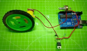
In this Arduino project, we are going to build an automatic speed controller for a DC motor using LDR with Arduino. This LDR-based Arduino project slows down the speed of the motor as the intensity of light falling on LDR decreases and vice versa.
By making this project, you will learn how to connect an LDR to Arduino as a sensor and control the speed of a motor using it. The program to ‘connect an LDR and motor with Arduino’ is also provided.
Watch the video tutorial below:
Table of Contents
Components required
- LDR or Light dependent resistor
- Arduino UNO
- TIP122 Transistor
- DC Motor
- 1 K ohm resistor
- 10 Kohm potentiometer
- Connecting wires
- 9-12V supply(optional)
Why use TIP122 transistor here?
We can’t connect the motor directly to the Arduino pins due to its low current capability. Hence TIP122 transistor is used here to switch the high-current motor using a low-current PWM signal from the Arduino pin.
The motor used here is rated at 5V and requires low current to operate. Hence the transistor(or motor) is powered from the Vin pin directly. If the voltage rating is > 5V, connect an external power supply(9V/12V) to Arduino using the DC jack and use the Vin pin. If the current rating of the motor is > 1A, use the supply to power the motor separately, i.e., don’t use the Vin pin.
Terminals of TIP122

Given below is the pinout of TIP122, which is similar to TIP120
- Collector in the middle
- Base terminal on the left
- Emitter terminal on the right

How to connect an LDR and motor with Arduino- Circuit diagram

To connect the LDR and DC motor with Arduino, follow these steps:
- Connect one end of LDR to the 5V pin of Arduino and the other end to the Analog pin A2.
- Connect the middle terminal of the potentiometer to Arduino’s ground and the end terminal(any) to analog pin A2.
- Connect the base of the transistor to the PWM pin 6, the emitter to the Arduino ground, and the collector to one end of the motor.
- The other end of the motor should be connected to the Vin pin if the current rating of the motor is less than 1A.
- If the motor requires low current and voltage under 5V, you may use the USB port for powering the Arduino. Use the DC jack to power the board from an external supply if the voltage rating is greater than 5V.
Program to connect an LDR and motor with Arduino
Given below is the program for the ‘Automated speed control of the DC motor using LDR’ project:
int x;  // input of LDR
int y;  // o/p Pwm value to be given to the base of the transistor to get reduced o/p voltage

void setup() {

  pinMode(A0, INPUT);
  pinMode(6, OUTPUT);
  Serial.begin(9600);
}

void loop() {
  x = analogRead(A0);           // analog input from the pin A0 connected to LDR and POT. end
  y = map(x, 0, 1023, 0, 255);  // Mapping or converting the value bw minimum to maximum analog value to the pwm value
  analogWrite(6, y);            // Writing this analog value to pin 6 which is connected to the base of the transistor to get reduced o/p voltage
  Serial.print("LDR input ");
  Serial.print(x);

  Serial.print("\t");

  Serial.print(" O/P PWM value ");
  Serial.print(y);
  Serial.println();

  delay(1000);
}
Working
1. When light falls on the LDR, the resistance of the LDR changes. This change in resistance causes a shift in the voltage drop across the LDR. Now, as the potentiometer is connected in series with the LDR, i.e., to Analog pin A0 to Ground, the voltage drop across it also undergoes changes. This alteration in voltage drop is captured by Analog pin A0 in the form of an analog value, ranging anywhere between 0 and 1023.
2. This received analog value is then converted to a PWM value between 0 and 255 by Arduino using this piece of code:
y= map(x,0,1023,0,255); // Mapping or converting the value bw minimum to maximum analog value to the corresponding pwm value3. This PWM value is now given to the digital pin 6, which is connected to the base of the transistor.
4. The command used to write this PWM value to pin 6 is:
analogWrite(6,y); // Writing this analog value to pin 6 5. This PWM signal switches the transistor ON and OFF.
6. As the PWM duty cycle varies due to the change in resistance across the LDR, the speed of the motor changes accordingly.
if I want to add 3 LEDs, where should the led be put