Last updated on March 19th, 2024 at 12:57 pm
TIP120 is a popular NPN Power Darlington transistor. It is widely used by engineers and hobbyists for general-purpose amplification and low-speed switching. It is capable of switching load up to 60 V with 5 Amps of the continuous collector to source current.

It is an NPN Darlington transistor because it has a Darlington pair inside of it which consists of two transistors. The output signal from the first transistor is further amplified by the second transistor to give a high overall current gain.

Table of Contents
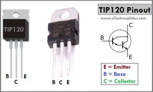
TIP120 Transistor Pinout
TIP120 pinout has three pins: emitter, base, and collector respectively from left to right(flat side with the leads pointed downward).

Datasheet
Given below is the datasheet of the TIP120 transistor in the T0-220 package:
Electrical characteristics, current-voltage ratings, and physical dimensions of the transistor are given in detail in this datasheet.
TIP120 equivalent
Given below is the list of popular transistors which can be used as a replacement for TIP120:
TIP122 is a good alternative to TIP120. Whereas 2N3904, BC547, BC538, 2N4401, and 2N2222A are low-power options.

Specifications
| Feature | Value |
| Type | NPN Power Darlington transistor |
| Package | TO-220 |
| Collector-Base voltage | 60 V |
| Collector-Emitter voltage | 60 V |
| Emitter-Base voltage | 5 V |
| Peak-load current(IC) | 8 A |
| Continuous load current(IC) | 5 A |
| Junction Temperature range | -65 to +150 °C |
TO-220 Package dimensions of TIP120:
All the dimensions shown below are in mm (minimum and maximum values).

How to use TIP120 transistor with Arduino?
This transistor is a popular choice when it comes to high-current DC load switching applications because it is widely available and easy to use.
Arduino can supply a small base current to the TIP120 transistor to switch ON the high current load connected between the external power supply and the collector terminal.
DC Motor speed control project

In this example, a DC motor speed is controlled using TIP120 with Arduino. You can use any other load like a lamp or solenoid in place of the motor.
A potentiometer is used to set the speed of the dc motor. Arduino takes analog input from the potentiometer and sets the voltage across the load according to it.
To use TIP120 with Arduino follow these steps:
- Connect the Arduino to the transistor using the required components as shown in the circuit diagram above
- Load can be a Motor, a lamp, solenoid etc.
- Base of the Transistor is connected to the Digital PWM pin 3 of the Arduino UNO here. But you can connect it to any other PWM pin according to the Load PWM frequency OR switching frequency requirements.
To know more about Arduino PWM frequency change, read this article.
Upload the code given below to your Arduino board:
/*
  DC Motor speed control using TIP120 with Arduino and potentiometer
*/

int motorPin = 3;       // the pin that the motor is attached to
int pot = A0;     // potentiometer is connected to analog pin 0

void setup()  {
  // declare pin 3 and A0 to be an output and input respectively:
  pinMode(motorPin, OUTPUT);
  pinMode(pot, INPUT);
  Serial.begin(9600);          //  setup serial
}

int getPotValue() {
  int potAnValue = analogRead(pot);    // read the input pin
  int potPWMValue = map(potAnValue, 0, 1023, 0, 255); // mapping to get 0 to 255
  if (potPWMValue < 50)
    potPWMValue = 0;
  else
    potPWMValue = min(potPWMValue, 255);
  // below PWM value 50 use 0 to avoid rough run
  return potPWMValue;
}

// the loop routine runs over and over again forever:
void loop()  {
  // set the PWM value on pin 3 for motor speed control
  analogWrite(motorPin, getPotValue());
  // print out getPotValue to serial monitor
  Serial.println(getPotValue());
  // 20 ms delay (can add noticible delay if over 200ms)
  delay(20);
}
Now, you should be able to control the speed of the DC Motor using a TIP120 transistor.
Mr Lazrak.w,
Would you like to give more explanations about this program for this project so we can understand the sense of differents stages of this program .thank you so much.
Hi,
Which part do you need help with?