Last updated on March 27th, 2024 at 05:04 pm
Arduino Uno is one of the most commonly used development boards these days. It can be used for almost any application that one can think of. One such application is in high-frequency circuits.
But to use a controller in a high-frequency circuit like in a buck converter, the controller must be able to generate high-frequency PWM waves. And if the controller you are using is Arduino Uno, then you must know how to change the frequency of these pins.
Now there are many facts about Arduino with which many students are not familiar. One of the facts is this:
“There is a certain default frequency for each PWM pin, which is called when the analogWrite command is used on that pin. And this default frequency can be changed to a value as high as 65Khz and as low as 30Hz by using just one line code“.
PWM frequency change on other Arduino boards
You can also watch this video for quick reference:
Here is the default frequency of each PWM pin of Arduino UNO:
1) PWM frequency for D3 & D11:
490.20 Hz (The default)
2) For D5 & D6:
976.56 Hz (The default)
3) For D9 & D10:
490.20 Hz (The default)
These frequencies are optimum for low-frequency applications like fading an LED. However, these default frequencies are not suitable for High-frequency circuits. For example, 1Khz is nothing when it comes to an S.M.P.S.
There are many projects in which we require high-frequency pulses. One such project is a Buck Converter. So to achieve a frequency lower or higher than the default one, a one-line code you can use to change it is given below:
One line code for changing PWM frequency on D3 & D11 pins:
TCCR2B = TCCR2B & B11111000 | B00000001; // for PWM frequency of 31372.55 Hz

TCCR2B = TCCR2B & B11111000 | B00000010; //  3921.16 Hz

TCCR2B = TCCR2B & B11111000 | B00000011; // 980.39 Hz

TCCR2B = TCCR2B & B11111000 | B00000100; //  (default)

TCCR2B = TCCR2B & B11111000 | B00000101; //  245.10 Hz

TCCR2B = TCCR2B & B11111000 | B00000110; //  122.55 Hz

TCCR2B = TCCR2B & B11111000 | B00000111; //  30.64 Hz
One line code for changing PWM frequency on D5 & D6 pins:
TCCR0B = TCCR0B & B11111000 | B00000001; // for PWM frequency of 62500.00 Hz

TCCR0B = TCCR0B & B11111000 | B00000010; //  7812.50 Hz

TCCR0B = TCCR0B & B11111000 | B00000011; //  (default)

TCCR0B = TCCR0B & B11111000 | B00000100; //  244.14 Hz

TCCR0B = TCCR0B & B11111000 | B00000101; //  61.04 Hz
One line code for changing PWM frequency on D9 & D10 pins:
TCCR1B = TCCR1B & B11111000 | B00000001; // set timer 1 divisor to 1 for PWM frequency of 31372.55 Hz

TCCR1B = TCCR1B & B11111000 | B00000010; //  3921.16 Hz

TCCR1B = TCCR1B & B11111000 | B00000011; // 490.20 Hz (default)

TCCR1B = TCCR1B & B11111000 | B00000100; //  122.55 Hz

TCCR1B = TCCR1B & B11111000 | B00000101; //  30.64 Hz
Example
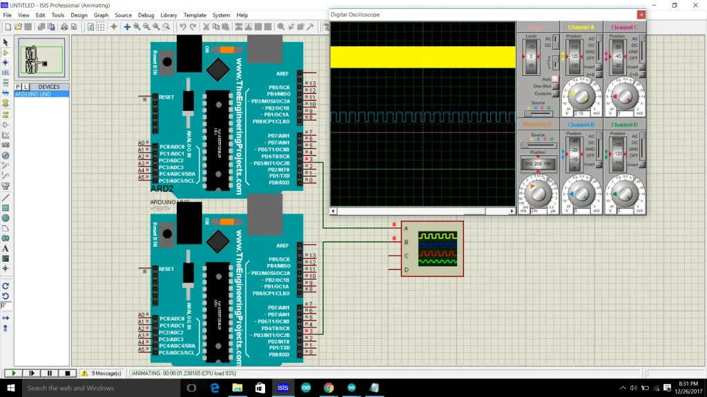
Let’s use the above code to change the frequency on pin D3. The circuit is simulated in proteus software.
Check out: How to add Arduino library to Proteus
Step 1: Two Arduino are selected and placed on the front panel.
Step 2: Digital Pin 3 ( PWM pin) of each Arduino is connected to the oscilloscope.
Step 3: Two separate programs are written for each Arduino. The first one outputs the PWM signal at a default frequency. For the second board, it is set to 31372.55 Hz using the command given above.
Program for Arduino1 – Default frequency on Pin 3
void setup() {

pinMode(3,OUTPUT);
// put your setup code here, to run once:

}

void loop() {
analogWrite(3,155);
// put your main code here, to run repeatedly:}
Program for Arduino2 – Changing the default frequency on D3
void setup() {

TCCR2B = TCCR2B & B11111000 | B00000001; // for PWM frequency of 31372.55 Hz
pinMode(3,OUTPUT);
}

void loop() {
analogWrite(3,155);
}
Step 4: Run the simulation

As you can see in the image given above, the second board(at the top) outputs the PWM signal at a higher frequency than the first board.
Learn more about Timers and PWM from here
FAQs
What is the PWM frequency of Arduino?
The PWM frequency of Arduino UNO and Nano is 490Hz for pins D3, D9, D10, and D11 and 980Hz for pins D5 and D6.
How to control PWM in Arduino?
To control PWM, the command analogWrite(PWM pin, duty cycle) is used. There are 6 PWM pins on Arduino UNO and Nano- 3,5,6,9,10 and 11. The duty cycle varies between 0 to 255.

How do I set the duty cicle?
Hi
many thanks for the tutorial.
Would you please let me know how I can implement these in LIFA_Base (LabVIEW interface)? I copied the relevant code e.g. “TCCR0B = TCCR0B & B11111000 | B00000101; // for PWM frequency of 61.04 Hz” but was not successful.
Best regards
MY
Thanks brother, it helped a lot.
your given codes works perfectly.
I checked the frequency on PicoScope.
rise and fall time was also under 10 microseconds(80/20%).
Thanks once again.
by Himanshu
You can actually make much slower pwm signals (with variable duty cylcle), here’s an example of 1Hz at pin 9 or 10:
void setup() {
DDRB |= _BV(PB1) | _BV(PB2); /* set pins 9 and 10 as outputs */
TCCR1A = _BV(COM1A1) | _BV(COM1B1) | _BV(WGM11) ; /* mode 10: PWM, phase correct, 16-bit */
TCCR1B = _BV(CS12) | _BV(WGM13); /* 256 prescaling */
ICR1 = 0x7918; /* TOP set to 31000 in order to get 1Hz */
}
void loop() {
OCR1A = 0x1E46; // 25% duty cycle
delay(1000);
}
Hi Brusk,
Thankyou for the suggestion. It will surely help other hobbyist.
How to change the desired switching frequency such as 25kHz, 50kHz ???
It helped to stop whining noise from DC motor. Thanks much
how to make a varity frequency