Last updated on January 5th, 2026 at 01:58 pm
The Arduino Uno is an open-source microcontroller board that is based on the Microchip ATmega328P (for Arduino UNO R3) or Microchip ATmega4809 (for Arduino UNO WIFI R2) micro-controller by Atmel and was the first USB-powered board developed by Arduino.
Both Atmega328 and ATmega4809 have a built-in bootloader, which makes it very convenient to flash the board with our code. Like all Arduino boards, we can program the software running on the board using a language derived from C and C++. The easiest development environment is the Arduino IDE.


Table of Contents
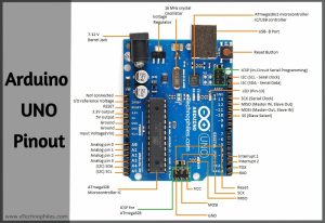
Arduino UNO Pinout
Arduino UNO R3 pin diagram shows that it has 6 analog inputs, 14 digital input/output pins (of which 6 can be used as PWM outputs), a 16 MHz ceramic crystal resonator, a USB-B port, an ICSP header, Atmega328p and Atmega 16U2 processor, a power jack and, a reset button.


The functions of different pins on the Arduino uno pin diagram are shown in the table below. We have discussed the detailed pinout at a later stage in this article.
| Pin Type | Pin Number | Total pins |
| Ground pins | 3 | |
| Digital Pins | D0 – D13 | 14 |
| PWM Pins | D3, D5, D6, D9, D10, D11 | 6 |
| Power output | 3.3V, 5V | 2 |
| Analog Pins | A0 – A5 | 6 |
| Serial Pins(UART) | RXD: D0, TXD: D1 | |
| External Interrupt Pins | D2, D3 | 2 |
| SPI Pins | SS : D10 COPI : D11 CIPO : D12 SCLK : D13 | 1 SPI interface |
| I2C protocol | SDA: A4 SCL: A5 | 1 I2C protocol |
| Built-in LED Pin | D13 |
Arduino UNO Specifications

Given below is the brief info about the specs of the latest Arduino UNO Rev3 board like the Microcontroller used, number of digital/analog pins, memory, voltage, and current ratings, etc.
| Microcontroller | ATmega328P |
| Operating Voltage | 5V |
| Input Voltage (recommended) | 7-12V |
| Input Voltage (limit) | 6-20V |
| Digital I/O Pins | 14 (of which 6 provide PWM output) |
| PWM Pins | 6( Pin 3, 5, 6, 9, 10, and 11) |
| Analog Input Pins | 6 |
| Communication protocol | UART x 1, SPI x 1, I2C x 1 |
| DC Current per I/O Pin | 20 mA |
| DC Current for 3.3V Pin | 50 mA |
| ICSP Header | 2 |
| Flash Memory | 32 KB (ATmega328P) of which 0.5 KB used by the bootloader |
| SRAM | 2 KB (ATmega328P) |
| EEPROM | 1 KB (ATmega328P) |
| Clock Speed | 16 MHz |
| LED_BUILTIN | 13 |
| Power Sources | Power Jack, USB port, Vin pin |
| Length | 68.6 mm |
| Width | 53.4 mm |
| Weight | 25 g |
Are you a beginner? Can’t decide which book to read? Check out this article on Best Arduino Books for beginners
What are the different parts of UNO?

Atmega328P Microcontroller– The ATmega328p is a single-chip, high-performance, efficient microcontroller created by Atmel in the megaAVR family. It is an 8-bit AVR RISC-based microcontroller chip. It consists of 32 KB ISP flash memory with read-while-write capabilities, 2 KB SRAM(Static RAM), 1 KB of EEPROM, 23 general-purpose I/O pins.
Atmega 16U2 Microcontroller– The Atmega 16U2 is used as a USB-to-serial converter in Arduino UNO.
Voltage Regulator-The voltage regulator converts the input voltage to 5V. The primary use of a voltage regulator is to control the voltage level in the Arduino board. Even if there are any fluctuations in the input supply voltage of the regulator, the output voltage remains constant and near 5 volts.

Crystal Oscillator– The Crystal oscillator has a frequency of 16MHz, which provides the clock signal to the microcontroller. It provides the basic timing and control to the board.
RESET Button–It is used to reset the board. It’s recommended to press this button every time we flash the code to the board.
Barrel Jack – The Barrel jack or DC Power Jack is used to power the Arduino board using an external power supply. The barrel jack is usually connected to an adapter. The board can be powered by an adapter that ranges between 5-20 volts but the manufacturer recommends keeping it between 7-12 volts.

Note: Above 12 volts, the board may overheat and below 7 volts, the voltage might not be sufficient to power the board.
USB B-port–The USB Interface is used to plug in the USB cable. This port can be used to power the device from the 5V supply. It allows us to connect the board to the computer. The program is uploaded to the board serially from the computer through the USB cable.
ICSP header– It stands for In-Circuit Serial Programming. We can use these pins to program the Arduino board’s firmware. The firmware changes with the new functionalities are sent to the microcontroller with the help of the ICSP header.
The ICSP header consists of 6 pins.
Pin description of Arduino Uno
I2C pins


I2C is the two-wire serial communication protocol. It stands for Inter-Integrated Circuits. The I2C uses two lines to send and receive data: a serial clock pin uses (SCL) and a serial data (SDA) (SDA) pin.
- SCL-It stands for Serial Clock. It is the pin or line that transfers the clock data. It is used to synchronize the shift of data between the two devices (master and slave). The Serial Clock is generated by the master device.
- SDA-It stands for Serial Data. It is defined as the line used by the slave and master to send and receive the data. That’s why it is called the data line, while SCL is called a clock line.
SPI pins

SPI stands for Serial Peripheral Interface. It is used by microcontrollers to communicate with one or more peripheral devices quickly.
- SCK-It stands for Serial Clock. These are the clock pulses, that is used to synchronize the transfer of data.
- MISO-It stands for Master Input/ Slave Output. This data line in the MISO pin is used to receive the data from the Slave.
- MOSI-It stands for Master Output/ Slave Input. This line is used for sending data to the peripherals.
- SS-It stands for Slave Select. This line is used by the master. It acts as the enable line. When a device’s Slave Select pin value is LOW, it can communicate with the master. When it’s value HIGH, it ignores the master. This allows us to have multiple SPI peripheral devices sharing the same MISO, MOSI, and CLK lines.
External Interrupts (2 and 3)- These pins can be used to trigger an interrupt on a low value, a rising or falling edge, or a change in value.
TXD and RXD-TXD and RXD pins are used for serial communication. The TXD is used to transmit the data, and RXD is used to receive the data. It also represents the successful flow of data.
ICSP pins

It stands for In-Circuit Serial Programming. We can use these pins to program the Arduino board’s firmware. The firmware changes with the new functionalities are sent to the microcontroller with the help of the ICSP header.
The ICSP header consists of 6 pins.

Analog pins

The Arduino Uno consists of 6 analog pins, which use ADC (Analog to Digital converter). These pins can serve as analog inputs but can also function as digital inputs or digital outputs. These pins accept inputs in the form of Analog signals and return values that range between 0 and 1023 (because the Arduino Uno has a 10-bit Analog to Digital converter or 210 resolution).
An Analog to digital converter works in three stages: sampling, quantization, and digitization. Because the Arduino operates on a 0–5 volts range, the step size of the device is 5/1023=0.00488volts or 4.88mV.
Thus, we can interpret a 4.88 mV input voltage to any of the analog pins as 1, 9.77 mV as 2, and so on until 5 V as 1023. Anything below 4.88 mV is considered 0 and above 4.99 V as 1023.
Digital Pins

On the Arduino UNO board, pins 0-13 are digital input/output pins.
The Arduino digital pins can read only two states: when there is a voltage signal and when there is no signal. This kind of input is usually called digital (or binary) and these states are referred to as HIGH and LOW or 1 and 0.
LED (13): On the board, there is a built-in LED connected to digital pin 13. When this pin is HIGH or 1, the LED is switched on, when the pin is LOW or 0, it’s switched off.
PWM pins

If you look closely, you will find the ‘~’ symbol on digital pin 3,5,6,9,10, and 11. These pins have an additional feature called PWM. Hence these pins are called PWM pins.
PWM stands for “Pulse Width Modulation”. It means, that an analog value is being modulated on a digital signal. Suppose you want a DC motor to run at a certain analog voltage between 0 and 5 V. This is not possible because the Arduino board is MOSFET-based.

Thus, to attain the desired output, we can only simulate an analog signal by switching our output on and off very quickly. Thus, PWM can only mimic and simulate the effects of a pure analog signal, it can never perform pure digital-to-analog conversion (which generally requires some active components like capacitors and inductors).
Other pins

GND (Ground pins): There are 5 ground pins available on the board.
RESET – Use to reset the Arduino Board. If this pin is supplied with 5 V, the board will reset automatically
I/O Reference Voltage (IOREF) – This pin is the input/output reference. It provides the voltage reference at which the microcontroller is currently operating. Sending a signal to this pin does nothing.
3.3V and 5V: These pins provide regulated 5v and 3.3v respectively to the external components connected to the board.
Vin–It is the modulated DC supply voltage, which is used to regulate the ICs used in the connection. It is also called the primary voltage for ICs present on the Arduino board. The Vcc voltage value can be negative or positive to the GND pin.
Where to Buy Arduino UNO?
You can get the original Arduino UNO board from different stores. But if you want to get it from Amazon, we recommend the following sellers:
![Arduino Uno REV3 [A000066] - ATmega328P Microcontroller, 16MHz, 14 Digital I/O Pins, 6 Analog Inputs, 32KB Flash, USB Connectivity, Compatible with Arduino IDE for DIY Projects and Prototyping](https://m.media-amazon.com/images/I/515P6aYSP4L.jpg)

Schematic of Arduino UNO Rev3(latest):
To download the updated Schematic version of the latest Arduino UNO Rev3, click here.

Dimensions of Arduino UNO:


Datasheet of Arduino UNO Rev3
Download the official Datasheet of Arduino UNO Rev3, from here.
FAQs
What is the full form of UNO in Arduino UNO?
UNO refers to the number 1 in Latin. Yes, it’s a Latin word and does not have any full form. Since this was the first official Arduino board released by the company, hence the word UNO in it.
Is Arduino a Microcontroller or a Microprocessor?
Arduino UNO is neither a microprocessor nor a microcontroller. It is a development board that uses a microcontroller called Atmega328p to perform various functions. You can say, atmega328p is the brain of the Arduino UNO development board.
How many programs can Arduino UNO run?
Arduino UNO is a simple microcontroller board without any operating system or powerful processor. Unlike your laptop or mobile phone, it can run only one program at a time. Of course, you can add multiple tasks in a single program but they will be executed one by one.
How many pins are there in Arduino UNO?
If you take a look at the Arduino board you will find that there are a total of 32 pins on it(excluding the ICSP header). Out of these 32 pins, 14 are digital I/O pins, 6 are analog pins, 3 GND and single 5V,3.3V, Vin and reset pin, and more.