Last updated on March 26th, 2024 at 05:11 pm
The Arduino Nano development board was first released in 2008 by Arduino and is one of the most popular Arduino boards. It is based on the ATmega328 8-bit microcontroller by Atmel (Microchip Technology).
The Atmega328 comes with a built-in bootloader, which makes it convenient to flash the Nano board with a program. Atmega 328P-based Arduino Nano pinout and specifications are given in detail in this post.
Arduino Nano has the same functionality but is smaller in size than Arduino Uno. The other difference is that there is no DC power jack on Nano and is powered using a Mini-B USB cable instead of a standard one.

Arduino Nano boards are widely used in the field of robotics, embedded systems, and electronic projects where the required size of the microcontroller is small.
Table of Contents

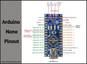
Arduino Nano pinout

Arduino Nano has a total of 36 pins. Out of these 8 are analog input pins and 14 digital input/output pins (of which 6 can be used as PWM outputs). Nano has a 16 MHz SMD crystal resonator, a mini USB-B port, an ICSP header, 3 RESET pins, and, a RESET button.
Atmega328P Microcontroller: The Atmega328P is a high-speed and efficient 8-bit microcontroller, which is based on AVR (Audio Video Recorder) RISC (Reduced Instruction Set Computing) Architecture. It is considered to be the most popular AVR controller. It consumes less power than the Atmega328 Microcontroller.

**Read more about the Atmega328p microcontroller here
SMD Crystal: The Surface Mount crystals have better stability than other crystals and can be easily soldered onto the PCB board.
| Looking for Arduino Nano PWM frequency change? |
Specifications
Given below are the technical specifications of the Arduino Nano.
| Microcontroller: | ATmega328 |
| Operating voltage: | 5 V |
| Input voltage (VIN): | 6-20 V |
| Power consumption: | 19 mA |
| Flash memory: | 32 KB (of which 2 KB is taken by bootloader) |
| SRAM: | 2 KB |
| Clock speed: | 16 MHz |
| EEPROM: | 1 KB |
| Current per I/O pin: | 40 mA (20 mA recommended) |
| PCB size: | 18 x 45 mm |
| Weight: | 7 g |
Pin description of Arduino Nano
Below is a comprehensive description of the Arduino Nano pinout.
Power pins

Mini USB: The Mini USB is smaller than the standard USB but thicker than the micro USB. The Nano board is powered through this port. It also allows us to connect the board to the computer for programming purposes.
Vin: It is the modulated DC supply voltage, which is used to regulate the ICs used in the connection. It is also called the primary voltage for ICs present on the Arduino board. The Vcc voltage value can be negative or positive to the GND pin.
Digital pins

There are 14 digital I/O pins on Arduino Nano. The Arduino digital pins can read/output only two states: when there is a voltage signal and when there is no signal. This kind of input/output is usually called digital (or binary) and these states are referred to as HIGH or 1 and LOW or 0.
Are you a beginner? Can't decide which book to read? Don't worry! Check out this article on Best Arduino Books for beginners.
PWM pins

If you look closely, you will find the ‘.’ symbol on digital pins 3,5,6,9,10, and 11. There are six pins from the set of digital pins that are PWM (Pulse Width Modulation) pins.
They are numbered as D3, D5, D6, D9, D10, and D11. Every one of these digital pins can generate a Pulse Width Modulation signal of 28-bit resolution. PWM pin generates the PWM signal using the analogWrite() function.
Analog pins

Arduino Nano has eight analog pins numbered from A0 to A7. You can connect up to 8 analog/digital sensors to the board.
The function of Analog pins is to read the value of the analog/digital input used in the connection. Each of these analog pins has an inbuilt ADC of resolution of 210 bits (so it will give 1024 values).
ICSP pins
The ICSP header consists of 6 pins:

It stands for In-Circuit Serial Programming. We can use these pins to program the Arduino board’s firmware. The firmware with the new functionalities is uploaded to the microcontroller with the help of the ICSP header.
I2C pins
It is the two-wire serial communication protocol. It stands for Inter-Integrated Circuits. The I2C uses two lines to send and receive data: a serial clock pin (SCL) and a serial data (SDA) (SDA) pin.
- I2C Pins on the board: A4(SDA), A5(SCL)
- SCL-It stands for Serial Clock. It is defined as the line that transfers the clock data. It is used to synchronize the shift of data between the two devices. The Serial Clock is generated by the master device.
- SDA-It stands for Serial Data. It is defined as the line used by the slave and master to send and receive the data. That’s why it is called a data line, while SCL is called a clock line.
SPI pins

SPI pins on the board: D13(SCK), D12(MISO), D11(MOSI)
SPI stands for Serial Peripheral Interface. It is used by the microcontrollers to communicate with one or more peripheral devices quickly.
- SCK-It stands for Serial Clock. These are the clock pulses, that are used to synchronize the transfer of data.
- MISO-It stands for Master Input/ Slave Output. This data line in the MISO pin is used to receive the data from the Slave.
- MOSI-It stands for Master Output/ Slave Input. This line is used for sending data to the peripherals.
- SS-It stands for Slave Select. This line is used by the master. It acts as the enable line. When a device’s Slave Select pin value is LOW, it can communicate with the master. When its value HIGH, it ignores the master. This allows us to have multiple SPI peripheral devices sharing the same MISO, MOSI, and CLK lines.
External Interrupts (2 and 3)- These pins can be used to trigger an external interrupt in the following conditions: a low value, a rising or falling edge, or a change in value.
UART Pins: TXD and RXD pins are used for serial communication. The TXD is used for transmitting the data, and RXD is used for receiving the data during serial communication. It also represents the successful flow of data from the computer to the board.
UART pins on board: D0(TX), D1(RX)
Other pins
3.3V: This pin outputs 3.3V.
5V: This pin outputs 5V.
GND (Ground pins): There is a total of 5 ground pins on the board..
RST: Use to reset the Arduino Board. If this pin is supplied with 5 V, the board will reset automatically
REF: This pin is the input/output reference. It provides the voltage reference at which the microcontroller is currently operating. Sending a signal to this pin does nothing.
LED Indicators on Arduino Nano
Arduino Nano board consists of 4 LED indicators:
Transmitting Data Indicator LED (White): When this LED is ON, the Arduino Nano is transmitting data to the computer.
Receiving Data Indicator LED (Red): When this LED lights up, the board is receiving data from the computer.
Power Indicator: It indicates the status of the battery. It can also display the voltage of the battery on the LCD connected to the Arduino board.
Pin 13 LED Indicator (Blue): In the board, there is a built-in LED connected to digital pin 13. When this pin is set to HIGH or 1, the LED turns ON. When the pin is set to LOW or 0, the LED turns OFF.
FAQs
What is 3V3 in Arduino Nano?
In Arduino Nano, “3V3” refers to the 3.3-volt regulated power supply output.
How do I power my Arduino Nano?
You can power your Arduino Nano through
1. USB connection.
2. External power supply connected to VIN or 5V pin.
3. 3.3V pin for components requiring 3.3V.
Which IC is used in Arduino Nano?
The Arduino Nano typically uses an ATmega328P microcontroller as its main integrated circuit (IC).
In arduino nano …I2C communication’s pins are A4,A5..
You have mentioned wrong.
Hi Sarthak,
Thank you for pointing out the mistake. Much appreciated 🙂
As for the error, it has been resolved now.
Salve vorrei progettare un cronometro con fotocellula usando arduino uno e arduino nano con nrf24l01 + e nn riesco trovare niente in rete come collegarle e come programmare.
Grazie