Last updated on March 26th, 2024 at 12:09 pm
The Arduino Nano RP2040 was released in 2021. This board came into existence after the release (and too much hype) of Raspberry pi Pico by the Raspberry Pi Foundation.
The Raspberry pi pico is based on their first microcontroller chip, RP2040. And Arduino Nano RP2040 Connect uses the same RP2040 microcontroller chip as its brain.


Table of Contents
This board has a U-blox® NINA-W102 radio module which can be used to make great Internet of Things projects with Bluetooth and WiFi connectivity. Arduino Nano Connect has an onboard accelerometer, gyroscope, RGB LED, and microphone.

The RP2040 microcontroller of Arduino Nano RP2040 Connect has a dual-core Arm Cortex M0+ processor running at 133MHz. It has an SRAM of 264 KB, and 16MB of flash memory. This article aims to give you an introduction to the Arduino Nano RP2040 Connect pinout, technical features, specifications, schematic and datasheet, etc.

**image courtesy Arduino.cc
So the new Arduino Nano RP2040 Connect is way more powerful than a Raspberry pi pico because it not only has an RP2040 chip with two Arm cortex MO+ processors but also a dual-core ESP32 with wifi and Bluetooth capability. Of course, it comes with a hefty price tag of $25 which is almost 6 times the cost of pico.
Board overview of Arduino nano RP2040 connect

RP2040 microcontroller chip
As already mentioned at the beginning of the article, this board comes with an RP2040 microcontroller chip. It is a custom-designed processor chip by the Raspberry Pi Foundation.

RP2040 is a powerful but cost-effective processor, featuring a dual-core Arm Cortex-M0+ processor running at 133Mhz. This is useful in projects where parallel processing is required at low power consumption.
The internal RAM of RP2040 is 264 KB and has 16MB of onboard flash memory.
A wide range of flexible I/O operations is possible including I2C, SPI, and Programmable general-purpose I/O (GPIO).
Download the datasheet of RP2040 from here.
Nina W102 wifi-Bluetooth module
The Nina W102 module provides wifi and Bluetooth connectivity to this Arduino board.
It has its microcontroller inside, an ESP32 microcontroller\ chip. And gives you full WiFi connectivity based on 802.11b/g/n IEEE standards along with Bluetooth connectivity and BLE v4.2.

The onboard RGB led(common anode) is driven using this module.
The analog pins A4 to A7 are connected to the 12-bit ADC of the Nina W102 module. Whereas analog pins A0 to A3 are connected to the 12-bit ADC of RP2040.
Since the original nano board has 8 analog pins, to make the RP2040 connect board similar to it, the analog pins of the RP2040 are expanded to 8 using the Nina W102 module.
The module has an inbuilt PCB antenna, thus eliminating the need for an external antenna.
Microphone MP34DT05 MEMS
MP34DT05 microphone module is based on MEMS or Micro-Electromechanical Systems. It is also known as a “Solid-state microphone”.

MP34DT05 is an omnidirectional microphone.
The output data given by MP3DT05 is in pulse density modulation format. And is connected to the RP2040 using an I2C bus.
LSM6DSOXTR 6-axis IMU or Initial measurement unit

The Arduino Nano RP2040 connect has an inbuilt LSM6DSOXTR 6-axis IMU. This 6-axis IMU provides data from a 3D gyroscope as well as a 3D accelerometer built inside it.
The interesting feature is that it is also possible to do machine learning on the IMU for gesture detection.
ATECC608A cryptographic IC
ATECC608A is a Cryptographic Co-Processor IC with Secure Hardware-Based Key Storage for up to 16 keys or certificates in its built-in EEPROM.

This IC provides Hardware Support for Symmetric Algorithms of type:
SHA-256 & HMAC Hash including off-chip context save/restore
AES-128: Encrypt/Decrypt, Galois Field Multiply for GCM
Micro USB port
The Arduino Nano RP2040 Connect board can be powered either using this Micro USB port or the onboard Vin pin. The acceptable input voltage range is between 5 to 21 volts.
Power LED
The board has a red power LED which indicates the ON/OFF status of the board.
Inbuilt LED
The board has an inbuilt orange LED connected to the digital pin 13.
RGB LED
Apart from the power and built-in LED, the Arduino Nano RP2040 has an RGB LED. This RGB LED is a common anode LED and is controlled using the NINA-W102 module.
Reset Button
The reset button resets the board when pressed. This button is connected to the active-low RESET pin of the RP2040 microcontroller chip using a pull-up resistor.
NOTE: This board is a 3.3-volt logic device and is not 5-volt tolerant as all the peripherals work on 3.3V logic.
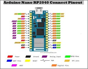
Arduino nano RP2040 connect pinout

As shown in the Arduino Nano RP2040 Connect pinout image given above, there are a total of 20 digital I/O pins, 8 Analog pins. Out of these, 18 pins can be used as a PWM pin(except A6 and A7) or to generate an interrupt(except A6 and A7).
Arduino Nano RP2040 connects power pins

**image courtesy Arduino.cc
Vin pin
This board can be powered either using this Micro USB port or this onboard Vin pin.
The acceptable input voltage range is between 5 to 21 volts. But a DC to DC buck converter converts this input voltage to a stable 3.3 volts before giving it to the RP2040 microcontroller.
When the board is powered through the Micro USB port, this voltage is reflected at the Vin pin also.
3V3 pin
3V3 pin gives constant 3.3 volts which can be used to power sensors and other devices. The input voltage given to the board is converted to a stable 3.3 volts using a DC to DC buck converter.
This onboard buck converter provides 3V3 to the RP2040 microcontroller and all other peripherals such as the Nina W102 module, MP34DT05 MEMS microphone, and LSM6DSOXTR 6-axis IMU, etc.
5V pin
This 5V pin is internally connected to the Micro USB port voltage pin(VUSB). So make sure you are using a stable 5V supply at the USB port input.
Note: To get 5 volts output from this pin, you need to short the VBUS jumper on the back of the board. And while powering the board from the VIN pin, you won’t get any regulated 5V, even after soldering the VBUS bridge.
GND pins
There are only two Ground pins available on this Arduino Nano RP2040 Connect board.
Digital pins
There are a total of 14 digital pins on the board. Starting from the digital pin D0 to all the way up to digital pin D13( the digital pins D0 and D1 are used for serial communication).
All of the digital pins on this board operate at 3.3 volts.
The digital pins can read one of the two states: when the electric signal is present and when it is absent. This type of input is usually known as digital type (or binary) and these states are referred to as HIGH(1) or LOW(0).
Note: These digital pins are 5V intolerant. So be careful while hooking up sensors and actuators to any of them.
Analog pins
This Arduino board has 8 analog inputs, labeled as AX (where X is pin no.). All of these pins can also be used as digital I/O pins.
Each one of the analog pins is connected to an inbuilt ADC of 212-bit (i.e., 1024 different values) resolution.
The analog pins A4 to A7 are connected to the 12-bit ADC of the Nina W102 module. Whereas analog pins A0 to A3 are connected to the 12-bit ADC of RP2040.Since the original nano board has 8 analog pins, to make the RP2040 connect board similar to it, the analog pins of the RP2040 are expanded to 8 using the Nina W102 module.
Note: Pins A4 and A5 are connected to an internal pull-up resistor and are used as an I2C Bus by default. So using these pins as analog inputs is not recommended.
PWM pins
If you look closely, you will find the ‘~’ symbol above each of the digital pins. These pins have an additional feature called PWM. Hence these pins are called PWM pins.
Note: All pins except A6 and A7 are available as PWM pins and can generate a PWM signal.
PWM stands for “Pulse Width Modulation”. It means that an analog value is being modulated on a digital signal. Suppose you want a DC motor to run at a certain analog voltage between 0 and 3.3 V. This is not possible because the Arduino board is MOSFET-based.
Thus, to attain the desired output, we can only simulate an analog signal by switching our output on and off very quickly. Thus, PWM can only mimic and simulate the effects of a pure analog signal, it can never perform pure digital to analog conversion (which generally requires some active components like capacitors and inductors).
Specifications and features
| Microcontroller | Raspberry Pi RP2040 | |
| USB connector | Micro USB | |
| Pins | Built-in LED pin | 13 |
| Digital I/O Pins | 20 | |
| Analog Input Pins | 8 | |
| PWM pins | 20 (Except A6, A7) | |
| External interrupts | 20 (Except A6, A7) | |
| Connectivity | Wi-Fi | Nina W102 uBlox module |
| Bluetooth | Nina W102 uBlox module | |
| Sensors | IMU | LSM6DSOXTR (6-axis) |
| Microphone | MP34DT05 | |
| Power | Circuit operating voltage | 3.3V |
| Input Voltage (VIN) | 5-21V | |
| DC Current per I/O pin | 4 mA | |
| Communication | UART (D0 and D1) | Yes |
| I2C (A4 and A5) | Yes | |
| SPI ( ) | Yes | |
| Clock speed | Processor | 133 MHz |
| Memory | AT25SF128A-MHB-T | 16MB Flash IC |
| Nina W102 uBlox module | 448 KB ROM, 520KB SRAM, 16MB Flash | |
To download the datasheet of this development board, click here.
Schematic
To download the schematic of Arduino Nano RP2040 Connect in PDF format, click here.
The schematic of the Nano RP2040 shows that the two MCUs(RP2040 and ESP32) share an I2C bus to which the inertial measurement unit (the IMU) and the authenticator device or secure element(ATECC608A Cryptographic Co-Processor IC) are connected. This means both the MCUs can use these.
The two MCUs also share the SPI and UART buses. The onboard RGB LED is connected to the ESP32 MCU while the microphone is connected to the RP2040 MCU.
Note: The analog pins A4 and A5 are used for the I2C communication protocol, and a 4.7K ohm pull-up resistor is connected to each of them.
Dimensions
The size/dimensions of this Arduino board are 43.18mm x 17.77mm.

Programming Arduino nano RP2040 connect
Since this is an Arduino board, it can be programmed via the Arduino IDE and online Arduino web editor. The Nano RP2040 board is also compatible with the Arduino cloud and Arduino IoT smartphone remote app. It can also be programmed using Micropython just like the Raspberry Pi pico.
Where to buy?
You can get the original Arduino Nano RP2040 Connect board from Arduino’s official store.

FAQs
Is RP2040 compatible with Arduino?
Yes, the RP2040 is compatible with Arduino. Arduino provides a core package for RP2040, enabling programming through the Arduino IDE and utilizing Arduino libraries. This compatibility ensures access to Arduino’s extensive ecosystem, including libraries, shields, and development tools, for RP2040-based boards.
What language is used in RP2040?
The RP2040 microcontroller primarily uses C/C++ for programming. It also supports languages like MicroPython and CircuitPython for flexibility in development.
Does RP2040 have Wi-Fi?
No, the RP2040 microcontroller does not have built-in Wi-Fi.