The ESP32 development board has an inbuilt Bluetooth module. In this post, I will show you how to use the ESP32 Bluetooth module with Arduino IDE. And by the end of this article, you would be able to use the ESP32 Bluetooth module with Arduino IDE to control external LEDs connected to the GPIO pins.
As we have discussed in the article on ESP32 dev board pinout, the ESP32 board along with the inbuilt Wi-Fi module also comes with an inbuilt Bluetooth module. This makes communication with mobile devices using the ESP32 Bluetooth module with Arduino IDE quite easy and efficient.
ESP32 Bluetooth module project details:
In this project, you will control the external LEDs connected to one of the GPIO pins of ESP32 using Bluetooth communication between the ESP32 board and the smartphone.
Note: I am going to use a mobile app called Serial Bluetooth terminal to control the LEDs.
| << Previous Tutorial: |
Materials Required:
- ESP32 Module
- Arduino IDE
- Micro USB cable
- Jumper Wire
- 1 x 100-ohm resistors
- 1 x LED
- Bluetooth Serial Monitor App
Circuit Diagram:
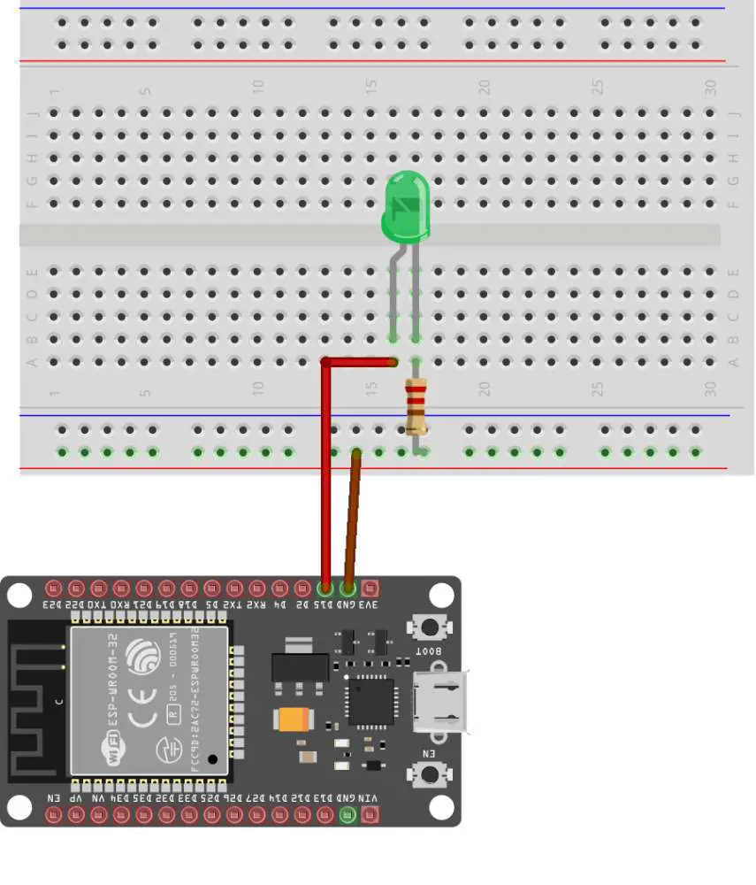
Step 1: Connect the ESP32 board to your PC through a micro-USB cable. The inbuilt RED LED on the board is turned on once the board is connected.
Step 2: Open up the Arduino application on your PC, go to Tools> Board from the top menu and click on the “ESP32 Arduino” option. Now select the type of ESP32 board you are using. I have selected the ESP32 dev module.
Step 3: Now go to Tools>Port, and select the port to which the board is connected to the PC (example COM4).
Step 4: Paste/write the ESP32 Bluetooth program given below in Arduino IDE.
#include "BluetoothSerial.h"
BluetoothSerial SerialBT;
char receivedChar;// received value will be stored as CHAR in this variable

const char turnON ='ON';
const char turnOFF ='OFF';
const int LEDpin = 15;

void setup() {
  Serial.begin(115200);
  SerialBT.begin("ESP32_Bluetooth"); //Bluetooth device name
  Serial.println("The device started, now you can pair it with bluetooth!");
  Serial.println("To turn ON send: ON");//print on serial monitor
  Serial.println("To turn OFF send: OFF"); //print on serial monitor
  pinMode(LEDpin, OUTPUT);
}
void loop() {
  if (Serial.available()) {
    SerialBT.write(Serial.read());
  }
  if (SerialBT.available()) {
    receivedChar =(char)SerialBT.read();
    SerialBT.print("Received:");// write on BT app
    SerialBT.println(receivedChar);// write on BT app
    Serial.print ("Received:");//print on serial monitor
    Serial.println(receivedChar);//print on serial monitor
    delay(10);
    if(receivedChar == turnON)
    {
     SerialBT.println("LED ON:");// write on BT app
     Serial.println("LED ON:");//write on serial monitor
     digitalWrite(LEDpin, HIGH);// turn the LED ON
     delay(20);
    }
    if(receivedChar == turnOFF)
    {
     SerialBT.println("LED OFF:");// write on BT app
     Serial.println("LED OFF:");//write on serial monitor
      digitalWrite(LEDpin, LOW);// turn the LED off
      delay(20);
    }
  }
}
Step 6: Click the upload option to upload the code. Don’t forget to press and hold the BOOT button during the uploading process.
Step 7: Open the serial monitor on the Arduino IDE by going to Tool>Serial Monitor or by pressing Ctrl+Shift+M.
Step 8: Press the RESET button on the ESP32 board.
Step 9: Now it’s time to switch to the mobile device that we are going to use to control the LED. Download the Bluetooth Serial Terminal App.

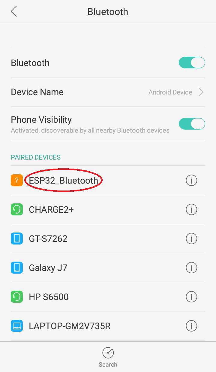
Step 10: Next pair up the ESP32 board with the mobile device.
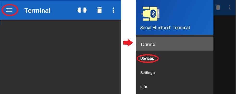
Step 11: Now open up the Bluetooth Serial Terminal App and go to Menu> Devices.
Step 12: Select the name of the ESP32 board that you want to connect. I am going to select “ESP32 Bluetooth”.
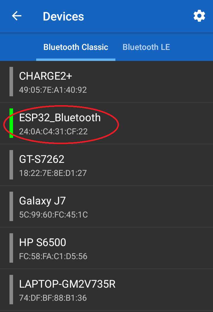
Step 13: Now as the ESP32 board is connected with the mobile device, we can communicate with it by sending serial data.
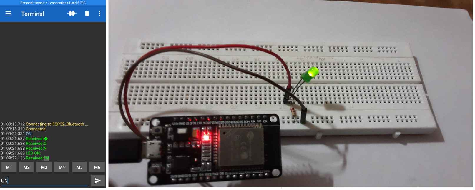
- Send “ON”: To turn ON the LED
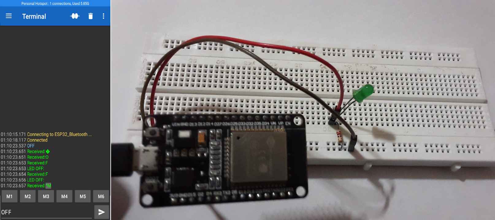
- Send “OFF”: To turn OFF the LED
Code Explanation:
#include "BluetoothSerial.h"
- #include is used to include outside libraries in our program. This gives the user access to a large group of standard C libraries (groups of pre-made functions), and also libraries written especially for the ESP32 board.
- Here, we have included the <BluetoothSerial.h> library that allows us to use functions that help us to connect the ESP32 board to other mobile devices.
BluetoothSerial SerialBT;
Create an object of class BluetoothSerial to initialize the Bluetooth stacks (controller and host) and to establish the serial communication over Bluetooth.
char receivedChar;
A char variable to store the value sent by the Bluetooth Serial terminal
const char turnON ='ON';
const char turnOFF ='OFF';
Variable to store turnOn and turnoff variables.
const int LEDpin = 15;
Assign the variable to the GPIO PIN.
Inside the void setup() function:
Serial.begin(115200);
- Serial.begin() function is used to initiate the serial data communication between the Arduino board and the Arduino IDE.
- The Serial.begin() function take the argument “data rate” to set up the communication speed for serial data transmission. Here we are setting the data rate as 115200 bits per second.
- Supported baud rates are 300, 600, 1200, 2400, 4800, 9600, 14400, 19200, 28800, 31250, 38400, 57600, and 115200.
SerialBT.begin("ESP32_Bluetooth");
This line begins the Bluetooth serial communication initialize with the name “ESP32_bluetooth“.
NOTE: You can change the name of the ESP32 board Bluetooth module using this line.
pinMode(LEDpin, OUTPUT);
Here, we are initializing the mode of LEDpin GPIO pin as OUTPUT.
Inside the void loop() function:
The void loop() function consists of two main instances of if statement
if (Serial.available()) {
SerialBT.write(Serial.read());
}
The first if statement is used to check whether the data is being received in the serial port or not. If the data is being received, send it to the connected device through Bluetooth.
if (SerialBT.available())
{
 .....
}
In the second if statement, we check if the data is being received in the Bluetooth serial port.
Now as both the if statements are executed means the connection between the ESP32 board and the mobile device is working fine.
receivedChar =(char)SerialBT.read();
Initialize the receivedChar variable with the data sent by the mobile device.
SerialBT.print("Received:");// write on BT app
SerialBT.println(receivedChar);// write on BT app
Print the successful message on the Bluetooth serial monitor app about the data received by the Bluetooth serial port.
Serial.print ("Received:");//print on serial monitor
Serial.println(receivedChar);//print on serial monitor
Also, print the successful message on the Arduino serial monitor about the data received by the serial port.
delay(20);
Delay the execution of the program by 20 milliseconds to overcome any lag between the received data.
Now there are two instances of if statement to control the GPIO pin connected to the LED.
if(receivedChar == turnON){
SerialBT.println("LED ON:");// write on BT app
Serial.println("LED ON:");//write on serial monitor
digitalWrite(LEDpin, HIGH);// turn the LED ON
delay(20);
}
- The first if statement compares the value received from the mobile device with the variable turnON (that is initialized as “ON”).
- If the value received is “ON”, a success message is printed in both the serial monitor as well as the Bluetooth serial monitor app about LED being turned ON. And also, the LEDpin is set to HIGH which results in switching ON of green LED.
if(receivedChar == turnOFF){
SerialBT.println("LED OFF:");// write on BT app
Serial.println("LED OFF:");//write on serial monitor
digitalWrite(LEDpin, LOW);// turn the LED off
delay(20);
}
- The second if statement compares the value received from the mobile device with the variable turnOFF (that is initialized as “OFF”).
- If the value received is “OFF”, a success message is printed on both the serial monitor as well as the Bluetooth serial monitor app about LED being turned OFF. And also, the LEDpin is set to LOW which results in switching OFF of green LED.
OBJECTIVE: To control the external LED connected to the ESP32 board.
