Last updated on March 26th, 2024 at 01:19 pm
ESP32 is a series of powerful, power-efficient, cheap microcontrollers that come with integrated Wi-Fi and dual-mode Bluetooth. In this post, you will find the ESP32 Dev board Pinout, Specifications, datasheet, and Schematic in detail.
The ESP32 series consists of a Tensilica Xtensa LX6 32-bit, dual-core microprocessor(has two processors) running at 240MHz and includes built-in antenna switches, RF balun, power amplifier, low-noise receive amplifier, filters, and power management modules.
ESP32 was developed by a semiconductor-based company Espressif Systems in China, and it is manufactured by TSMC (Taiwan Semiconductor Manufacturing Company). It is a successor to their previous ESP8266 microcontroller module.
**Want to learn ESP32 through the traditional method? Check out our blog post on the best Esp32 books for beginners!
Table of Contents
Introduction to ESP32 development board
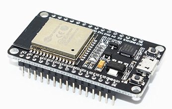
NOTE: The details given here hold true for all development boards: NodeMCU ESP32-S board by AI Thinker, ESP32 DOIT board by Espressif, Sparkfun ESP32 Thing board, Adafruit ESP32 board, etc.
ESP WROOM-32 Chip: The ESP32 board comes with a powerful WROOM-32 module having capabilities like 802.11b/g/n Wi-Fi |BT 4.0|BLE. The chip consists of a dual-core processor, and both can be controlled individually, operating at 240Mhz, 520KB of SRAM. It is compatible with Arduino IDE, LUA, MicroPython, etc.
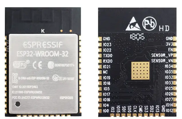
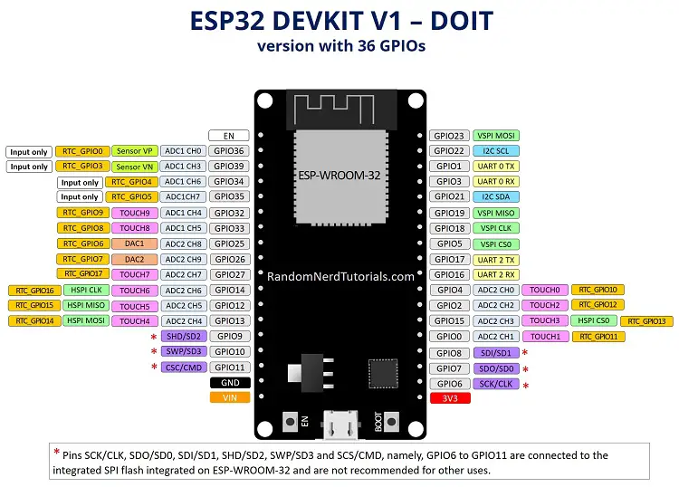
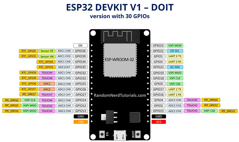
NOTE: Not all development boards expose all the pins on the chip. The original ESP32 microcontroller or IC has 48 pins. The ESP32 breakout board(WROOM-32) shown above has 38 exposed pins of the IC. This WROOM-32 chip is then further used in ESP32 boards with only 30 or 36 exposed pins (available for external connection).
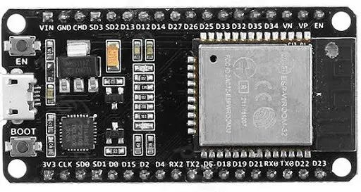
Boot Button: This button is used to upload the new sketch/programs to the ESP32 microcontroller. During the upload, we have to HOLD down the Boot Button.
Micro USB: The board is powered using an onboard Micro USB port. This port can also be used to connect the board to the computer to upload programs.
RESET Button: This button is simply used to reset the board.
Touch Sensor: The ESP32 comes with 10 capacitive touch sensors connected to GPIO pins-
- Touch0 (GPIO4)
- Touch1 (GPIO0)
- Touch2 (GPIO2)
- Touch3 (GPIO15)
- Touch4 (GPIO13)
- Touch5 (GPIO12)
- Touch6 (GPIO14)
- Touch7 (GPIO27)
- Touch8 (GPIO33)
- Touch9 (GPIO32)
These GPIO pins can sense variations if they touch anything that conducts electricity, like the human skin. So, when we touch the GPIO pin with our finger, it generates this variation that is read by the sensor. We can use the touchRead(GPIO) function to read the value from the touch sensor.
Hall Effect Sensor: The board comes with another built-in sensor, a Hall effect sensor. Hall effect sensor is used to measure the change in the magnetic field in the surroundings.
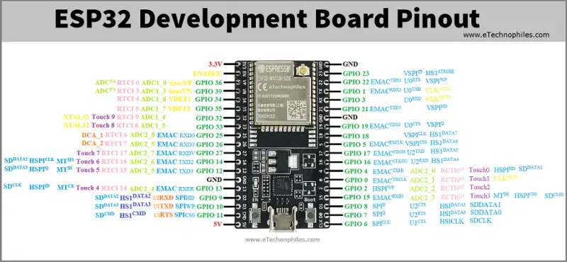
ESP32 Dev board pinout:
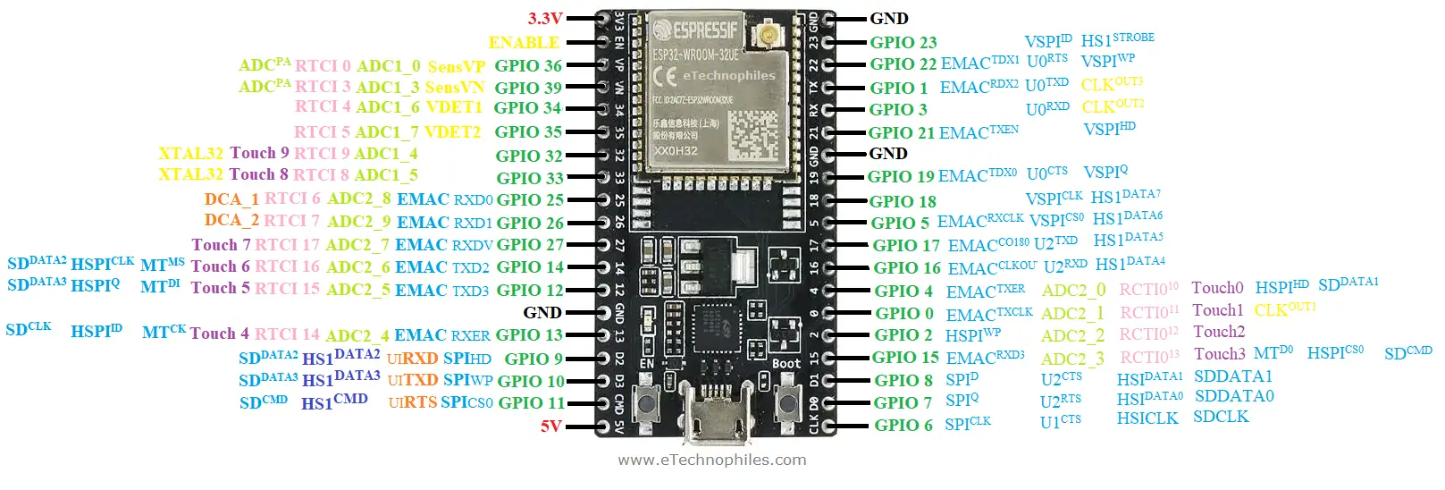
**Download the HD Pinout image from here.
The ESP 32 board given above exposes all 38 pins of the Wroom-32 chip. Out of these 38 pins, 30 pins are GPIO pins that can be used for a number of different functions.
Power Pins:
The board comes with two power pins – a 5V pin & a 3.3V pin. The 5V pin can be used to directly supply the ESP32 and its peripherals if you have a regulated 5V voltage source. While the 3.3V pin is the output of a voltage regulator (CP2102), it can be used to power up the external components.
GND: The ground pin of ESP32 is used to complete the circuit.
ADC (Analog to digital) Channels:
The board has 18 12-bit SAR ADCs and supports measurements on 15 channels (analog enabled pins. ADC1_CH0 (GPIO 36)
- ADC1_CH1 (GPIO 37)
- ADC1_CH2 (GPIO 38)
- ADC1_CH3 (GPIO 39)
- ADC1_CH4 (GPIO 32)
- ADC1_CH5 (GPIO 33)
- ADC1_CH6 (GPIO 34)
- ADC1_CH7 (GPIO 35)
- ADC2_CH0 (GPIO 4)
- ADC2_CH1 (GPIO 0)
- ADC2_CH2 (GPIO 2)
- ADC2_CH3 (GPIO 15)
- ADC2_CH4 (GPIO 13)
- ADC2_CH5 (GPIO 12)
- ADC2_CH6 (GPIO 14)
- ADC2_CH7 (GPIO 27)
- ADC2_CH8 (GPIO 25)
- ADC2_CH9 (GPIO 26)
DAC (Digital to Analog) Channels:
The board comes with two 8-bit DAC channels that can be used to convert digital signals into analog voltage.
- DAC_1 (GPIO25)
- DAC_2 (GPIO26)
UART (Universal Asynchronous Receiver-Transmitter) Pins:
ESP32 dev board has three UART interfaces, – UART0, UART1, and UART2, which provide asynchronous communication between the UART-enabled devices up to a speed of 5 Mbps.
UART interface in the dev board also consists of two extra pins that allow the receiver and sender to alert each other of their current state – CTS and RTS signals pins.
UART0 Pins
- U0 TXD (GPIO1)
- U0 RXD (GPIO3)
- U0 CTS (GPIO19)
- U0 RTS (GPIO22)
UART1 Pins
- U1 TXD (GPIO10)
- U1 RXD (GPIO9)
- U1 CTS (GPIO6)
- U1 RTS (GPIO11)
UART2 Pins
- U2 TXD (GPIO17)
- U2 RXD (GPIO16)
- U2 CTS (GPIO8)
- U2 RTS (GPIO7)
SPI Pins
The board features three SPIs (SPI, HSPI, and VSPI) in slave and master modes. These pins are used to connect to the external SPI-enabled devices.
SPI Pins on board
- SPI_D (GPIO8)
- SPI_WP (GPIO10)
- SPI_HD (GPIO9)
- SPI_Q (GPIO7)
- SPI_CLK (GPIO6)
- SPI_CS0 (GPIO11)
HSPI Pins
- V_SPI_ID (GPIO23)
- V_SPI_WP (GPIO22)
- V_SPI_HD (GPIO21)
- V_SPI_Q (GPIO19)
- V_SPI_CLK (GPIO18)
- V_SPI_CS0 (GPIO5)
VSPI Pins
- HSPI_ID (GPIO13)
- HSPI_WP (GPIO2)
- HSPI_HD (GPIO4)
- HSPI_Q (GPIO12)
- HSPI_CLK (GPIO14)
- HSPI_CS0 (GPIO15)
PWM Pins
The board comes with 25 PWM-enabled pins (Nearly All GPIO pins). The PWM output can be used for driving digital motors and LEDs.
EN or Enable Pin
EN stands for Enable; this is a 3.3 V regulator enable pin. When this is pulled LOW, is a 3.3 V regulator enable pin. When this is pulled LOW, it resets the microcontroller.
NOTE: The dev board discussed above has 38 pins. The two other popular variants have only 30 or 36 pins exposed(available for external connection), although they have the same WROOM-32 chip installed.
**Images source: RandomNerdTutorials
Where to Buy ESP32 Boards?
You can get the ESP32 board from different stores. But if you want to get it from Amazon, we recommend the following sellers:


Datasheet of ESP32 Wroom 32
**To download the datasheet of ESP Wroom 32, click here.
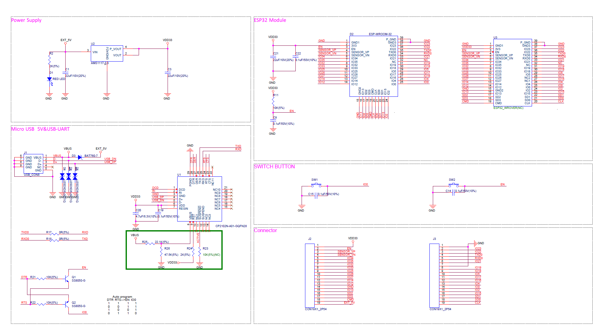
Schematic of ESP32 Dev Board:
**To download the schematic of ESP32, click here.
Specifications of ESP32 Board:
- Xtensa dual-core (or single-core) 32-bit LX6 microprocessor, running at 160 or 240 MHz
- Memory: 520 KB SRAM
- Wi-Fi: 802.11 b/g/n
- Bluetooth: v4.2 BR/EDR and BLE
- 12-bit × 18 ADC channels
- 2 × 8-bit DACs
- 10 × touch sensors (capacitive sensing GPIOs)
- 4 × SPI
- 2 × I²S interfaces
- 2 × I²C interfaces
- 3 × UART
- SD/SDIO/CE-ATA/MMC/eMMC host controller
- SDIO/SPI slave controller
- CAN bus 2.0
- Infrared remote controller (TX/RX, up to 8 channels)
- Motor PWM
- LED PWM (up to 16 channels)
- Hall effect sensor
- Ultra-low-power analog pre-amplifier
- All security features of IEEE 802.11 standard, like WFA, WPA/WPA2, and WAPI, secure boot, Flash encryption
- Cryptographic hardware acceleration methods like AES, SHA-2, RSA, elliptic curve cryptography (ECC), random number generator (RNG)
P.S: Want to learn ESP32 through the traditional method? Check out our blog post on the best Esp32 books for beginners!