Last updated on March 23rd, 2024 at 01:12 pm
NodeMCU esp8266 wifi module is an open-source, low-cost, low-power MCU(microcontroller unit) development board. It has 17 GPIO pins(11 are Digital I/O pins), out of which one pin is an analog pin, 4 pins support PWM, 2 pairs are for UART(UART0 and UART1), and supports 1x SPI and 1x I2C protocol.
NodeMCU ESP8266 has 128Kb of RAM, 4 MB of Flash memory, and a maximum clock speed of 160MHz(80 -160). The operating current is 80mA(average).
The ESP8266 Integrates an 802.11b/g/n HT40 Wi-Fi transceiver chip for WiFi connectivity and gives it the additional advantage of creating its network thus allowing other devices to connect directly to it.
Note: When ESP8266 was released, its open-source firmware was called Nodemcu by the developers. But now the term “Nodemcu” usually refers to the ESP8266 Wifi module.
Table of Contents
Nodemcu versions or generations:
As of now, there are three official versions of the Nodemcu: Nodemcu Devkit 0.9 or Nodemcu V1, Nodemcu Devkit 1.0 or Nodemcu V2, and Lolin Nodemcu or Nodemcu V3.

Nodemcu Esp8266 packaging style
Two main packaging types of Nodemcu are available in the market: Amica and LoLin.
Amica Nodemcu package
The Amica Nodemcu has narrow pin spacing and measures 49mm x 26mm with a standard pin space of 0.1″ between pins and 0.9″ between rows.

LoLin nodemcu package
The Lolin Nodemcu has a wider pin spacing and larger board layout than the Amica package. It measures 58mm x 32mm with a pin spacing of 0.1″ between pins and 1.1″ between rows.

Note: The Amica NodeMCU is approximately 25% smaller in size than a closely compatible LoLin style NodeMCU.
Note: The LoLin board has 2 extra pins: VU and Ground pin. The VU pin is directly connected to the USB port power pin which can deliver 5V if the board is powered using a USB.
NodeMCU esp8266 wifi module is mostly used for IoT-based projects. By using NodeMCU ESP8266 Wifi Module, IoT applications become easier and cheaper.
Please note that the ESP8266 is a breadboard-friendly development board. And at its heart is a wifi module called ESP-12E. The ESP-12E is a tiny wifi module or the miniature version of ESP8266 that gives ESP8266 the functionality of Wireless communication. You can say, it is the brain of the ESP8266 Wifi module.
ESP8266 wifi module board layout
The Nodemcu wifi module comprises of ESP12E chip(the brain of the module), GPIO pins for easy interfacing, 3.3 Volt Voltage regulator, onboard LED, USB to serial converter IC, USB port, and more.

ESP8266-12E wifi chip with antenna
This esp8266-12E or simply esp-12E chip is a member of the esp-xx series. There are 15 modules ranging from esp01 to esp15. These are mostly used for IoT applications due to their small form factor and low price.
Processor: The latest ESP12E board integrates a Tensilica LX106 32-bit RISC processor, which achieves extra-low power consumption and reaches a maximum clock speed of 160 MHz.
Uploading a program in ESP-12E using the micro USB cable is difficult as it requires a separate 3.3 voltage regulator, reset button, some resistors, and a USB to TTL converter IC.
But the development board Nodemcu ESP8266 module has everything mentioned above, thus it is easy to program it from your laptop/PC. Nodemcu ESP8266 has an Esp12e chip, a USB port to upload programs, and for power supply. It also has a reset and boot button.
Hence the Nodemcu is a better choice over the esp12e chip as it is easy to use, is breadboard-friendly, and comes at the same price.
Voltage regulator AMS1117
The esp12e chip works on 3.3 Volts. But since a micro USB cable provides 5 Volts, the Nodemcu has an on-board 3.3 V voltage regulator which is AMS1117.
USB to TTL/serial converter
To program the board using a USB cable, the USB to TTL/UART converter IC is needed. Nodemcu ESP8266 has CP2102 USB to UART bridge controller IC (in SMD QFN-28 package). Some old ESP8266 boards use CH340G USB to TTL converter IC (in SMD SOP-16 package).
Usually, the Lolin Nodemcu has CP2102 and Amica Nodemcu has CH340G USB to TTL converter IC.
Flash button
The boot or flash button is used while uploading the program. If you hold it down and press the EN/RST, the ES8266 will restart in flashing/uploading mode

Nodemcu ESP8266 wifi module specifications
Let’s have a look at the specifications of NodeMCU.
| Microcontroller | ESP-8266 32-bit |
| NodeMCU Model | Amica(official) |
| Clock Speed | 80-160 MHz |
| USB to Serial | CP2102 |
| USB Connector | Micro USB |
| Operating Voltage | 3.3V |
| Input Voltage | 4.5V-10V |
| Flash Memory/SRAM | 4 MB / 128 KB |
| GPIO Pins | 17 |
| Digital I/O Pins | 11 |
| Analog In Pins | 1 |
| PWM Pins | 4 |
| ADC Range | 0-3.3V |
| UART/SPI/I2C | 2 / 1 / 1 |
| WiFi Built-In | 802.11 b/g/n |
| Temperature Range | -40C – 125C |
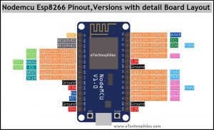
Nodemcu ESP8266 pinout

As shown in the above image, there is a total of 17 GPIO(General Purpose Input Output) pins. Out of which only 11 pins are best to use. These 11 pins are mentioned in the table given below. We can use those pins as an input or output.
| Pin Name | GPIO | Input | Output |
| D0 | 16 | pull-up | pull-up |
| D1 | 5 | OK | OK |
| D2 | 4 | OK | OK |
| D3 | 0 | pull-up | OK |
| D4 | 2 | pull-up | OK |
| D5 | 14 | OK | OK |
| D6 | 12 | OK | OK |
| D7 | 13 | OK | OK |
| D8 | 15 | pull-down | OK |
| RX | 3 | pull-up | NO |
| TX | 1 | NO | pull-up |
| A0 | ADC0 | Analog | NO |
Power pins
Vin: This pin can be used to power the esp8266 board. Up to 5V can be supplied to it. The Vin pin can be used to directly supply the Nodemcu esp8266 and its peripherals if you have a regulated 5V voltage source. This 5 volt is then converted to 3.3 volts using a voltage regulator as the esp12e chip requires 3.3V to operate.
Note: The Lolin ESP8266 module has one extra pin called VU. If the module is powered from a USB(5V), you can get 5V from the VU pin to power the external devices.
3.3 V: The board has three 3.3V pins. While the 3.3V pin is the output of a voltage regulator (CP2102), it can be used to power up the external components.
GND: There are a total of 4 such pins.
Note: All the GPIO pins of the ESP8266 are 3.3 V compatible(I/O) and are not 5V tolerant. Supplying 5 volts or more directly to any of the pins may damage the board.
ADC(Analog to digital) channel
ESP8266 has an inbuilt 10-bit ADC or analog-to-digital converter with only one ADC channel. In other words, the board has only one analog pin to read the analog voltage values from external devices like sensors and potentiometers.
This analog pin is marked as A0 on the board as given in the pinout diagram above.
UART (Universal Asynchronous Receiver-Transmitter) pins
The esp8266 board has 2 UART interfaces– RX0 and TX0 are UART0, RX2 and TX2 are UART1. The UART1 is used for uploading the firmware or program.
UART0 pins
- U0 TXD (GPIO1)
- U0 RXD (GPIO3)
UART1 pins
- U1 TXD (GPIO15)
- U1 RXD (GPIO13)
SPI pins
Unlike the three UART interfaces, the Esp8266 Nodemcu has only one set of SPI pins. The SPI protocol requires 4 pins: MOSI, MISO, SCLK, and CS.
- GPIO 7: MISO
- GPIO 8: MISO
- GPIO 6: SCLK
- GPIO 11: CS
I2C pins
The ESP8266 does not support any hardware I2C protocol, but it is possible to implement it in the programming part. So you may use any GPIO pins as I2C as long as you are aware of the I2C programming. Only two pins are required for I2C: SDA and SCLK.
Usually, the following GPIOs are used as I2C pins:
- GPIO 4: SDA
- GPIO 5: SCL
PWM pins
The board comes with 4 PWM-enabled pins. The PWM output can be used for driving digital motors and LEDs. PWM pins on the ESP8266 board are GPIO 4, GPIO 12, GPIO 14, and GPIO 15. OR digital pins D2, D5, D6, and D8.
EN or enable pin
EN stands for Enable, which enables the esp8266 chip i.e. ESP12E when pulled high. The chip works at minimum power when the EN pin is pulled low.
RST or reset Pin
This pin resets the board when pulled low. It works like the onboard reset button.
Wake pin(D0)
This pin is used to wake up the esp8266 chip from a deep sleep.
NOTE: EN, RST, and Wake pins are called the control pins of the ESP8266 board.
Nodemcu ESP8266 datasheet(ESP-12E):
To download the datasheet of this development board, click here.
Nodemcu dimensions
Amica nodemcu V2 dimensions:
The physical dimension of Amica or Nodemcu V2 is 4.8 X 2.6 in Centimeters.

LoLin nodemcu V3 dimensions:
The physical dimension of LoLin or Nodemcu V3 is 5.8 X 3.1 Centimeters.

FAQs
Why is ESP8266 used?
ESP8266 is used for its low-cost, integrated Wi-Fi capabilities, making it ideal for IoT projects and DIY electronics. Its small form factor, low power consumption, and ease of programming contribute to its popularity in applications like home automation, sensor networks, and remote monitoring.
Is NodeMCU and Arduino same?
No, NodeMCU and Arduino are not the same. NodeMCU is a development board based on the ESP8266 microcontroller, primarily used for IoT projects and Wi-Fi connectivity. Arduino is a popular open-source electronics platform based on various microcontrollers, offering a wide range of development boards for different applications.
What language is used for NodeMCU?
NodeMCU primarily uses Lua for programming, but C/C++ (via Arduino IDE) and MicroPython are also options.