Last updated on April 6th, 2024 at 11:56 am
The potentiometer is a widely used electronic equipment in the industry to create continuously variable voltage or resistance. The terms ‘Potential Difference’ and ‘Metering’ are combined to form the name potentiometer. It is also referred to as ‘potmeter’ and ‘pot’ in the electronics sector.
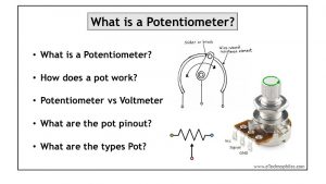
Table of Contents
What’s the principle of a Potentiometer?
The principle of a potentiometer is to vary the voltage across the circuit to generate the desired output. The basic principle behind its operation is similar to a voltage divider circuit. The potentiometer can also be used as a variable resistor. This feature of continuously varying potential is extensively used in types of equipment like radios and other audio-related devices for volume control.
Initially, pots were bulky apparatus, that had three terminals and consisted of a sliding contact to adjust the voltage. The variation in the output voltage was proportional to the position of the slider along the track. The potentiometers used now are very small and easy to handle with the circuits. They are also utilized as position transducers in the joystick.
Potentiometer symbol
The symbol of the potentiometer depicts its application in the circuits. It is symbolized in different ways concerning standardization. But, all these symbols convey the common idea, i.e., a variable resistor.
The pot in American Standard is denoted as a resistor symbol with an arrow above it. As per the International standard, the symbol of a potentiometer is a rectangular box with two terminals on either side and one above, which is shown in the figure.

Potentiometer pinout diagram
The pinout diagram of a potentiometer is shown in the figure below. The three pins depict the three terminals. The wiper slides on the resistive track to give a variable resistance across the output. The end terminals can be interchanged to VCC and Ground.

What is the difference between potentiometer and voltmeter?
Both potentiometer and voltmeter are used to measure the voltage in the circuit. But they differ in several aspects, which are listed in the table below:
| Potentiometer | Voltmeter |
|---|---|
| Three terminal device | Two terminal device |
| Measures EMF | Measures terminal voltage |
| More accurate and sensitive | Less accurate and sensitive |
| Do not give a direct reading | Gives a direct reading |

Is the potentiometer analog or digital?
The potentiometers are available in three types among which one is digital and the other two are analog. The major difference in their operation is that the variation in the resistance to control the current flow is performed manually in analog pots. Whereas the digital pot automatically varies the resistance as per the circuit requirements.
Analog potentiometer
Two major types of analog potentiometers are Rotary and Linear. The working principle of both these pots is similar, except that the sliding contact on the resistor moves in a circular motion in the first type and moves linearly in the latter type.
What are the types of Analog potentiometers?
There are two types of Analog potentiometers, Rotary and Linear potentiometers.
Rotary
The uniform resistance in the Rotary potmeter is in a circular pattern in which the two end terminals are at either side of the resistance. The third terminal is attached to the sliding contact which appears in the middle of the other two terminals.

Linear
The straight uniform resistance of the linear potentiometer serves as the two end terminals which are connected across the source voltage. The terminal at the sliding contact is the third terminal which is connected to the output circuit.

Digital potentiometers
As the name says, the digital potentiometers work on digital inputs and are commonly called ‘Digipots’. The function of a digital pot is similar to an analog pot, but the usage is more complicated than that of an analog type.
In some applications, analog potmeters face multiple challenges like size, mechanical wear, humidity, resistance drift, etc.
The digital potmeters, on the other hand, produce more accurate results as they do not have any moving parts. And hence, they are widely used for equipment calibration.
Types of digital potentiometer
Digital potentiometers are available in two types, which are volatile and non-volatile potentiometers.
In the non-volatile type, the potmeters are embedded with a memory unit like EPROM or flash memory with which it retains the last position of the slider, in case of a power failure. The volatile type has no such memory capacity and loses its final position when there is a power loss. The figure below shows the circuit for the digital potmeter.

Is a potentiometer a rheostat?
A potentiometer closely resembles the rheostat but the potentiometer is used to vary the voltage whereas the rheostat varies the current flow in the circuit.
Thus, while a potmeter is meant for variable voltage, rheostat takes the role of variable resistance. The potmeter itself can be used as a rheostat with a small change in the connection. It acts as a rheostat when only two pins, one end of the uniform resistance, and the sliding bar(linear)/wiper(rotary) are connected to the circuit.
For a better understanding, the figure below shows the difference in the connection between a pot and a rheostat.

Why does the potentiometer have 3 legs?
Pots have three legs or terminals to create a variable resistance or voltage. They have two fixed terminals connected internally across a uniform resistor. A third terminal, called the Wiper terminal is connected in between this uniform resistor. So when the wiper is rotated(rotary pots) or slid (linear pot), the resistance between any of the fixed terminals and this wiper terminal changes.

The following are the three pins of a potentiometer:
Pin 1: Positioned at one end of the uniform resistor(Fixed end).
Pin 2: Positioned at the slider/wiper to give variable voltage(Variable end).
Pin 3: Positioned at the other end of the uniform resistor(Fixed end).
Does a potentiometer change voltage or current?
The potentiometer is specifically meant to change the voltage across the circuit. But it can also be used to change the current flow by connecting it as a rheostat.
When the two terminals at the ends of uniform resistance are connected to the source voltage and the third sliding terminal is connected to the output circuit, it is connected as a potmeter to vary the voltage across the terminals. Whereas, if only one fixed terminal and the sliding point is used in the circuit it acts as a rheostat and changes the current flow in the circuit.
How to wire a potentiometer?
Wiring a rotary potmeter involves soldering each wire to the respective terminal. The wiring of a potmeter is done in three stages.
Stage 1: Preparing the potmeter
To prepare the potmeter for your project, follow the following steps.
- Identify the terminals
Before using any potmeter you need to set one end terminal as positive and the other terminal as negative. The middle terminal then becomes either Input or Output. For example: As a sensor input and as a voltage divider output.
- Identify the resistance
The resistance value of the potmeter is usually printed on its surface. It is important to note this value before using it in the circuit.
- Prepare the connection wire
Before soldering the wires to the potmeter, measuring and cutting them makes your task easy. Use Black, Red, and Orange wires for negative, positive, and middle terminals respectively.
Stage 2: Soldering
This step requires you to solder the wires to the potmeter.
- Connect the black wire to the selected negative terminal
- Solder the orange wire to the middle terminal.
- Connect the remaining terminal to the Red wire.
Stage 3: Potmeter in use
- Check the working of the potmeter by connecting to a voltmeter.
- Adjust the input using the knob and check the voltage variation through the connected voltmeter.
- Make sure you connect the black wire to the Ground of the circuit and
- The Red wire to the positive terminal of the circuit.
How to use potentiometer as a voltage divider or variable resistor?
Using as a Voltage divider
To use the potmeter as a voltage divider circuit, connect its end terminals across the voltage source. And the wiper terminal to one of the ends of the Load as shown below. The other end of the Load goes to the negative terminal of the voltage source. Now on moving the wiper terminal, voltage across the load changes.
The figure below depicts how a potmeter can be used as a voltage divider.

Using as a Variable resistor
To use a potmeter as a variable resistor, you need only two terminals (either of the end terminals and the middle terminal). These two terminals are inserted into the circuit just like a normal resistor. Now if you rotate the wiper terminal of the potmeter the resistance between the connected terminal changes. This way a pot is used as a variable resistor in a circuit.
How to use a potentiometer with Arduino?
The pot can be connected to the Arduino UNO board to read analog values as shown in the figure below. This way you can use the pot as a sensor, let’s say to change the brightness to the LED. The two fixed end terminals of the pot are connected to a fixed voltage and the middle terminal is connected to the analog pin.

Related: Potentiometer Wiring- 4 Simple Circuits using Potentiometer
Applications of potentiometer
Potentiometers take part in applications that require a gradual change in voltage or resistance. Some of the popular applications of potentiometers are listed below.
- Audio control: It is mostly used in radios for audio control. Linear, as well as rotary potentiometers, can be used as per convenience.
- Motion control: Pots are utilized to achieve a closed-loop control in position feedback device.
- Television: The control of picture brightness, contrast, and color response is achieved using a potentiometer.
- Transducers: They take part in the designing of displacement transducers.
- Computation
- To determine the internal resistance of a cell
- To compare the EMF of two cells