Last updated on March 23rd, 2024 at 11:01 am
OBD2 is an onboard diagnostic system present in cars that collect data from a vehicle. To collect this data, the cars must have an OBD port installed in them. Using an OBD connecter, a technician may collect this data and analyze the errors in the car. But, to see how all of this works, let us first understand what an OBD port and connector is.
Table of Contents
What is an OBD2 port?
It is a 16-pin OBD port present in your car that is used by the technician to find faults in the car. The technician connects an OBD2 connector to this port that converts the error data into readable format. This error data is gathered by the OBD2 system installed in the car.
What is an OBD2 connector?
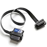
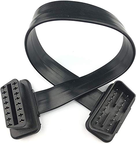
The OBD2 connector is one end of the OBD2 cable that goes to the OBD2 port of the car. The other end of the cable connects to the OBD2 scanner. This way the OBD2 adaptor cable reads the error codes from the OBD2 system and displays them on the scanner.
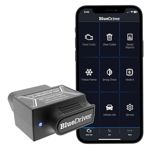
Sometimes this OBD2 connector comes attached to a Bluetooth scanner. Using this Bluetooth scanner, you can check data wirelessly from a laptop, mobile, etc.

It is used to get real-time data information and onboard diagnostics results. Each manufacturer uses its own OBD-II Diagnostic Link Connector (DLC) which is the main connector through which all subsystems are tuned, reprogrammed & diagnosed.
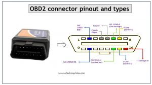
OBD2 connector pinout
OBD connector has 16 pins in a trapezoidal shape. The following diagram shows the picture of an OBD2 connector pinout.

The table below describes each pin:
| Pin Number | Pin Name | Description |
|---|---|---|
| 1,3,8,9,11,12,13 | Blank | These are non-standard and vendor-specific. These are not required for normal communication or interfacing. |
| 2 | SAE J1850 Bus+ | Bus positive pin of the protocol. It follows the protocol Variable Pulse Width and is usually used by GM vehicles. |
| 10 | SAE J1850 Bus- | Bus negative pin of the protocol. It follows the protocol Variable Pulse Width and is usually used by GM vehicles. |
| 4,5 | Ground | The ground of the Car system (including chassis). |
| 6 | ISO15765-4 CAN High | CAN High Pin. It follows a 2-wire CAN protocol at 1Mbps speed. |
| 14 | ISO15765-4 CAN Low | CAN Low Pin. It follows a 2-wire CAN protocol at 1Mbps speed. |
| 7 | ISO 9141 – K Line | K line pin. It follows an asynchronous serial communication protocol. |
| 8 | ISO 9141 – L Line | K line pin. It follows asynchronous serial communication protocol |
What are the types of OBD2 connectors?
There are two types of OBD2 connectors used in a vehicle, i.e., Type A and Type B.
Type A vs. Type B
- Type A is commonly found in cards, while Type B is common in heavy & medium vehicles.
- Both A & B types have similar OBD2 pinouts, but the output power supply is different: 12V for type A and 24V for type B.
- There is a difference in the Baud Rate. The cars use approximately 500K, while most heavy-duty vehicles use 250K.

Now let’s discuss these pins in a bit more detail.
SAE J1850 PWM
- SAE J1850 PWM protocol with connector pins 2 & 10.
- It produces a signal by pulse width modulation. It performs at the speed of 41.6 kb/sec and is mostly found in Ford vehicles.
- Pins 2, 4, 5, 10, and 16 should be of this type.
- PWM stands for Pulse Width Modulation. In PWM, an analog signal is changed into a digital signal in a different wave-like square wave.
SAE J1850 VPW
- For GM vehicles, SAE J1850 VPW is commonly used.
- It operates at a speed of 10.4 kb/sec by the variable pulse width.
- Pins 2, 4, 5, and 16 have SAE J1850 VPM. At pin no. 10 there is a difference between VPW and PWM is that this OBD2 protocol.
- VPM-It was developed by General Motors and it is an encoding method. It stands for Variable Pulse Width and its signal rate is 10.4 Kbps.
- VPM is more beneficial than the PWM scheme.
ISO 9141-2
- Old protocol
- Mostly used in European vehicles. Also in some Asian vehicles & in Chrysler.
- Its running speed is 10.4 kb/sec and it uses serial communication asynchronously.
- It is optional pins 7& 15 (pins 4, 5, and 16 are must-haves).
- ISO stands for International Organization for Standardization. This protocol represents voltage in a logic 0 or 1 form. Logic 0 represents low voltage and logic 1 represents high voltage. In this, each bit of information is 96 us long.
ISO 14230 KWP2000
- It operates at 10.4 kb/s. It is used for serial asynchronous communication.
- This protocol is most common in Europe and commonly in Chrysler. This protocol used in Asian vehicles having pin 7 Kline & pin 15 is optional.
- KWP is Keyword Protocol. It is used for communication protocol which is applied on the OBD system.
ISO 15765-4 CAN (SAE J2480)
- ISO 15765-4 CAN is available in vehicles that were built in 2008 or later in the US.
- Pins 4, 5, 6, 14, and 16 support this protocol.
- OBD2 protocol consists of 4 variants.
- It works on a 2-wire communication method.
- It can handle up to 1 Mbps.
CAN – stands for controller area network
- It refers to a network of independent controllers.
- The communication happens without a host computer.
- It uses a broadcast type of bus communication protocol.
What is an OBD2 code?
Whenever a problem is detected in a vehicle using the OBD, the system shows it as an error code. This code is called a Diagnostic Trouble Code (DTC).
If we try to interpret it, we can understand the cause of the problem. For example, a car shows the P0200 code, which means that there is a possible injector circuit issue. Now, this error can be pinpointed & can be fixed before the actual breakdown.
How to read OBD2 DTC codes?

OBD provides diagnoses for various systems such as powertrain, chassis, body, etc. By careful reading the letters & numbers, a fault can be found & fixed easily. Here the code is simplified as follows:
The first character
It is a letter that denotes the vehicle’s part that has a fault.
P – Powertrain.
- It includes the vehicle’s engine, transmission, and other associated accessories.
U – Network & Vehicle Integration
- It is managed by an onboard computer system.
B – Body.
- Parts are usually found in the compartment area of passengers in the vehicle.
C – Chassis.
- Consists of mechanical functions & systems example, braking, steering, and suspension.
The second character
It is a number that can be ‘0’, ‘1’, ‘2’, or ‘3’.
‘0’, ‘2’, or ‘3’
- standardized (SAE) code or generic code
‘1’
- Manufacturer specific code
The third character
It is a number or a letter that shows the system in the vehicle that has a fault.
0 – Emission controls: fuel and air metering
1 – Fuel & air metering
2 – Injector circuit: Fuel & air metering
3 – Ignition systems/misfiring
4 – Auxiliary emission control system
5 – Speed Control & idle control systems
6 – Computer and output circuit system
7 – Transmission system
A-F – Hybrid codes
Final: The fourth and fifth character
It is a two-digit number that defines the exact problem & can be any number between 0 and 99.
Where is the OBD2 port located in a car?
Since OBD port or diagnostic port location varies from manufacturer to manufacturer, it is usually found on the driver’s side under the dashboard. In some vehicles, it can be found near the center console section in a vehicle. In old models, this port can be found near the handbrake or in the trunk.

Once this port is found, we can easily plug the reader which establishes a connection between the vehicle and the diagnostic device.
Absolutely great post!
Very straightforward and helpful!
I’m considering buying the obd2 scanner. Your post helped me a lot.
Thanks for sharing.
Can I charge the battery through the OBD connection? ,I think pin 16
hello. I own a 1995 Mazda 323F BA AT 1.6 and the car has a different set of diagnostics. can you tell me how the system works, how to get and how to interpret them.
thank you.