Last updated on April 5th, 2024 at 05:38 pm
A potentiometer is one of the most widely used electronic components that have applications in audio circuits, motor speed control, instruments, etc. It is mainly wired as a voltage divider or variable resistor in a circuit. But there are plenty of other ways potentiometer wiring can be done.
We have listed 4 ways you can wire a potentiometer in this article.
Table of Contents
Potentiometer as a voltage divider
You can either make a fixed voltage divider or an adjustable one depending on the application.
How to make a fixed voltage divider?
A fixed voltage divider is made by applying an input voltage across two resistors connected in series. The remaining end of one resistor is set at high potential whereas the remaining end of the other resistor is grounded.

The voltage between the intermediate point and GND then gives the fraction of the input voltage required. Given by the formula:
Vout = Vin x (1/(R1+R2)) x R2
To create a voltage divider, you need to first fix one resistor and then calculate the other resistor depending on the required output voltage. To calculate the value of the required resistor, use this formula:
                                                         R2 = -VoutR2/(Vout-Vin)

                                                         R2 = VoutR2/(Vin-Vout)
This is called a fixed voltage divider because the output voltage is fixed i.e. you can’t its value without changing either the resistor value or input voltage.
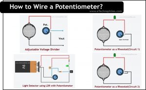
Potentiometer as an Adjustable voltage divider
The potentiometer is essentially two resistors connected in series with an adjustable wiper terminal. The resistance between this terminal and any of the end terminals can vary and so is the output voltage.

To create a voltage divider using the potentiometer, apply an input voltage across the potentiometer’s end. One end to +ve and the other end to ground. The voltage between the wiper terminal and the Ground is the required output voltage.
Here you have an additional feature- you can change the output voltage by changing the wiper position.
Potentiometer as a Rheostat
A potentiometer and a rheostat may seem similar but are not. Rheostat is one of the many applications of a potentiometer. Let’s see what a rheostat is and how it differs from a potentiometer.
What is a Rheostat?
A device that is used to vary the resistance in a circuit is called a Rheostat. Due to the change in resistance, the magnitude of the current also changes. So technically, a potentiometer can also be called a rheostat.
But a rheostat is used in high-power applications(hence bulkier) whereas a potentiometer is suitable for low-power applications.
The term ‘rheostat’ is now obsolete. ‘Potentiometer’ is widely accepted.
How to use a Potentiometer as Rheostat?
To use a potentiometer as a rheostat, you only need two terminals: any of the end terminals and the middle terminal. So when the wiper position changes, the resistance between these two points also changes.

As you can see, when used like this, one terminal always remains unconnected or open. This is not a major problem but while designing a PCB, the software may display a warning.
To solve this problem, the open terminal and middle terminal are connected. By doing this, nothing changes. The value of the resistance changes exactly like in the first circuit i.e. when the terminal is open.

You will find this wiring example of “potentiometer as a rheostat” in many circuit diagrams.
Potentiometer as a Sensor with Arduino
You can connect a potentiometer to an Arduino board to read analog values as shown in the figure below. As the wiper position changes, the input voltage value at analog pin A0 changes. Hence, the potentiometer acts as a sensor in this circuit.

You can do all sorts of stuff with this like turning on a certain LED (connected to Arduino) depending on the wiper position.
In the example circuit above, the program simply displays the analog value on the serial monitor.
Potentiometer with a sensor
You may find circuits where a potentiometer and other sensors are used together. It can be any sensor like an LDR as shown below or a flex sensor etc.

The reason for using a potentiometer here is to change the sensitivity of the circuit or sensor. In the example above, if the potentiometer gives maximum resistance, the voltage drop across the LDR will be minimal. The circuit becomes less sensitive in this case.
Whereas when the potentiometer gives minimum resistance, the voltage drop across the LDR will be maximum. The circuit becomes more sensitive in this case.