Last updated on March 26th, 2024 at 01:28 pm
Raspberry Pi Foundation is well known for its series of single-board computers (Raspberry Pi series). But in January 2021 they launched their first micro-controller board known as Raspberry Pi Pico.
It is built around the RP2040 Soc, a very fast yet cost-effective microcontroller chip packed with a dual-core ARM Cortex-M0+ processor. M0+ is one of the most power-efficient ARM processors.

Raspberry Pi Pico is a small, fast, and versatile board that at its heart consists of RP2040, a brand-new product launched by Raspberry Foundation in the UK. It can be programmed using MicroPython or C language.
Table of Contents
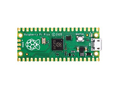
Raspberry Pi PICO board layout

Raspberry Pi Pico is made up of several components. The board layout given above shows some of them: RP2040 Microcontroller, Debugging pins, Flash Memory, Boot selection button, programmable LED, USB port, and power pin.
What is RP2040 Microcontroller Chip?
RP2040 microcontroller is a custom-designed processor chip by the Raspberry Pi foundation itself. It is a powerful but cost-effective processor, featuring a dual-core Arm Cortex-M0+ processor running at 133 MHz.
It has 264KB of internal RAM and support for up to 16MB of onboard flash memory.
A wide range of flexible I/O operations is possible including I2C, SPI, and Programmable general-purpose I/O (GPIO).
What is the meaning of RP2040?
The name of the RP2040 microcontroller is made up of 5 sections:
- RP in RP2040 means ‘Raspberry Pi’.
- 2 signifies the number of processor cores the microcontroller has i.e, 2 cores.
- 0 represents the type of processor core the RP2040 microcontroller has. This processor is called ARM Cortex-M0+ processor. Other microcontrollers of this series by ARM are named as Cortex-M1, Cortex-M3, Cortex-M4, Cortex-M7 etc.
- 4 means the microcontroller has has 264 kilobytes (kB) of RAM. Which is based on a special mathematical function: floor(log2(RAM/16)).
- 0 simply means there is no non-volatile storage on‑board.
Datasheet of RP2040
To download the datasheet of the RP2040 Microcontroller, click here.
Note: The Wifi version of the Pico board, called "Pico W" is now released. To know more about the Pico W(Wireless), click here.
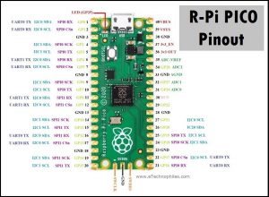
Raspberry Pi PICO Pinout

The Raspberry Pi Pico pinout shows that it has a total of 40 pins including GND and Vcc pins. The pins can be categorized as Power, ground, UART, GPIO, PWM, ADC, SPI, I2C, system control, and Debugging pins.
Unlike the Raspberry Pi computer board series, GPIO pins present on the Pico board have multiple functions.
For example, GP4 and GP5 pins can be either used as digital input or digital output or I2C1 (SDA and SCK pins) or UART1 (Rx and Tx). But only one function can be enabled at a time.
GPIO Pins
In Raspberry Pi Pico, out of 40 pins, 26 pins are multi-functional GPIO pins. These 26 GPIO pins can be used both as digital input and digital output. These digital pins are marked from GP0, GP1, and up to GP28.
The marked GP23, GP24, GP25, and GP29 are not exposed on the header. These GPIO pins are used for internal board functions:
| Pin | Function |
| GPIO29: | Used in ADC mode (ADC3) to measure VSYS/3 |
| GPIO25: | Output connected to the user LED |
| GPIO24: | IP VBUS sense – high if VBUS is present, else low |
| GPIO23: | OP Controls the on-board SMPS Power Save pin |
Analog Pins
The board comes with 4 analog pins with 12-bit ADC. Hence, we can use these pins to read analog inputs from various sensors.
But one out of these four pins(ADC 4) is not provided as a GPIO pin on the board. This fourth ADC pin is internally connected to a temperature sensor.
NOTE: Therefore, to measure the temperature we can directly use this build-in temperature by reading the analog value of ADC4.
ADC Pin GPIO Pins
ADC0 GP26
ADC1 GP27
ADC2 GP28
PWM Pins

Image source: www.RaspberryPi.org
- The Raspberry Pi Pico has 8 PWM blocks/slices(1-8) and each PWM block provides up to two PWM outputs(A-B). This means each block can drive up to two PWM outputs.
- Hence, there is a total of 16 PWM output channels available at a time and every GPIO pin on the pico is capable of generating PWM output.
- So all GPIO pins can be configured to get PWM signal output when required but two GPIO pins with the same PWM designation cannot be used at once.
NOTE: The above paragraph may seem confusing, but don't worry: all it means is that you must keep track of the PWM output signal and block you’re using, making sure not to use two GPIO pins having the same number and letter designation togetherWhat is the PIO feature in Pi Pico?
Pico’s Programmable Input/Output (PIO) feature lets you configure the input and output pins on Pico to suit your needs. This is done through a software interface, which means that no hardware changes are necessary.
The PIO can be used to control external devices, like sensors or motors. It can also be used to interface with other digital systems. The PIO is a powerful and versatile tool that lets users have a lot of control over their Pico’s behavior.
Each RP2040 has two PIO chips, and each chip can do things like small processors. They can do this by using instructions that are stored in shared PIO memory.
We can utilize the PIO instances to mimic more sophisticated peripherals that aren’t directly supported by the chip, such as the SD card interface, CAN Bus, and WS2812b driver. The PIO state machines run independently of the main CPU, allowing these simulated peripherals to communicate with external devices simultaneously with the primary program.
I2C Pins
I2C is a two-wire, bi-directional serial bus that provides an easy and quick method for transmission of transmission over a short distance between I2C-enabled devices.
The Raspberry Pi Pico comes with two I2C controllers, both I2C controllers are accessible through the GPIO pins of the Raspberry Pi Pico.
| I2C Controller | GPIO Pins |
| I2C0 SDA | GP0/GP4/GP8/GP12/GP16/GP20 |
| I2C0 SCL | GP1/GP5/GP9/GP13/GP17/GP21 |
| I2C1 SDA | GP2/GP6/GP10/GP14/GP18/GP26 |
| I2C1 SCL | GP3/GP7/GP11/GP15/GP19/GP27 |
SPI Pins
Serial Peripheral Interface (SPI) is an interface bus that is used to transfer data between the microcontroller and SPI-enabled devices. Raspberry Pi Pico supports two SPI interfaces that are accessible through the GPIO pins of the board.
| SPI Controller | GPIO Pins |
| SPI0_RX | GP0/GP4/GP16 |
| SPI0_TX | GP3/GP7/GP19 |
| SPI0_CLK | GP2/GP6/GP18 |
| SPI0_CSn | GP1/GP5/GP17 |
| SPI1_RX | GP8/GP12 |
| SPI1_TX | GP11/GP15 |
| SPI1_CLK | GP10/GP14 |
| SPI1_CSn | GP9/GP13 |
UART Pins
The Raspberry Pi Pico also contains two identical UART peripherals. UART (universal asynchronous receiver-transmitter) pins are used for asynchronous serial communication between the micro-controller and UART devices or other microcontrollers.
| UART Pins | GPIO Pins |
| UART0-TX | GP0/GP12/GP16 |
| UART0-RX | GP1/GP13/GP17 |
| UART1-TX | GP4/GP8 |
| UART1-RX | GP5/GP9 |
GPIO Interrupts on Pico
All GPIO pins on the board can be configured as an external interrupt if one of the following changes in the state of GPIO pins occur:
- Level high(+3v)
- Level Low(GND)
- Positive edge (transition from active low to active high)
- Negative edge (transition from active high to active low)
Other Pins on Pico board
GND: is the Ground pin used to complete the circuit.
VBUS: is the micro-USB input voltage it is connected to micro-USB port pin 1.
VSYS: is the main system input voltage, which can vary in the allowed range 1.8V to 5.5V, and is used by the on-board
SMPS: to generate the 3.3V for the board and its GPIO.
3V3_EN: connects to the onboard SMPS enable pin, and is set to high (to VSYS) connected through a 100K resistor. To disable the 3.3V(which also de-powers the RP2040), short this pin low.
3V3: is the main 3.3V supply to the board and its I/O, generated by the on-board SMPS. This pin can also be used to power external components.
ADC_VREF: is the ADC pin power supply voltage, and is generated by filtering the 3.3V supply coming through the board.
AGND: is the ground reference for GPIO26-29, there is a separate analog ground plane running under these signals and terminating at this pin. If the ADC pins are not used or ADC performance is doesn’t matter, this pin can be connected to digital ground.
RUN: is the RP2040 enable pin, and has an internal (on-chip) pull-up resistor to 3.3V of about ~50K Ohms. To resetRP2040, short this pin low.
Specifications of R-PI Pico
- Dual-core Arm Cortex M0+ processor running at 133 MHz
- Board comes with 264KB of SRAM, and 2MB of onboard Flash memory
- Comes with the castellated module that allows us to solder it directly to carrier boards
- USB 1.1 with device and host support
- Low-power sleep and dormant modes
- Drag-and-drop programming using mass storage over USB
- 26 × multi-function GPIO pins
- 2 × SPI peripherals, 2 × I2C controllers, 2 × UART peripherals, 3 × 12-bit ADC, 16 × controllable PWM channels
- Accurate clock and timer on-chip
- Temperature sensor
- Accelerated floating-point libraries on-chip
- It features 8 Programmable I/O (PIO) state machines for custom peripheral support
Read Similar Articles:
| Raspberry Pi 4 GPIO Pinout and Specs in detail
| Raspberry Pi Zero GPIO pinout and specifications in detail
Thank you for your most informative article!
Would you be able to add any further comment to help me better appreciate the concepts the Pico designers had in mind when they introduced the 8 PWM blocks / slices / channels ? What’s the idea behind having a PWM generator delivering two pins the same output (that is to say that it is my understanding of it: 8 PWM generators for 16 pins). What practical purpose comes to mind for this design ? Nb. having 8 PWM channels is a really great asset but I regret seeing 16 pins being claimed.
Thank you very much.
There are 8×2 PWM outputs, 16 independent channels PWM in total. But, as there are more GPIO pins (26) than PWM channels (16), some pins are connected to the same PWM channels. Say, GP0 and GP16 are connected both to PWM_A[0]. If you have configured GP0 as PWM, GP16 do the same.