Last updated on March 26th, 2024 at 01:45 pm
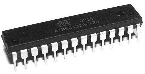
The ATmega328p is a single-chip, high-performance, efficient microcontroller created by Atmel in the megaAVR family. It is an 8-bit AVR RISC-based microcontroller chip.
In this post, we will learn about the ATmega328p pinout, its datasheet, specifications, and programming methods in detail.

It consists of 32 KB ISP flash memory with read-while-write capabilities, 2 KB SRAM(Static RAM), 1 KB of EEPROM, 23 general-purpose I/O pins, a 16MHz clock, 32 general-purpose working registers, three flexible timer/counters with compare modes (two 8 bits and one 16 bit), internal and external interrupts, serial programmable UART, a byte-oriented I2C (inter-integrated circuit) interface pins, SPI serial port, 6-channel 10-bit Analog to Digital converter, programmable watchdog timer with internal oscillator, and five software selectable power saving modes. The device operates between a voltage range of 1.8-5.5 volts.
Note: 328p in ATmega328p means: 32 for 32KB of flash memory, 8 for Bit RISC architecture(data bus), and p for “pico-power” (consumes less power under certain circumstances)
Table of Contents
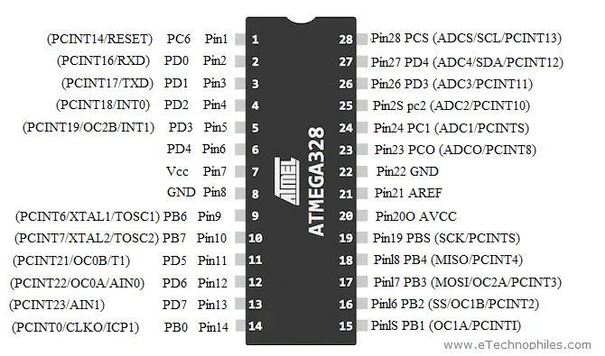
Atmega328P Pinout

| Pin No. | Pin Name | Pin Function | Pin Function Description |
|---|---|---|---|
| 1 | PC6 | Reset | This pin helps to reset the microcontroller. |
| 2 | PD0 | Digital Pin (RX) | This is the input pin for serial communication |
| 3 | PD1 | Digital Pin (TX) | This is the output pin for serial communication |
| 4 | PD2 | Digital Pin | It is used as an external interrupt 0 |
| 5 | PD3 | Digital Pin (PWM) | It is used as an external interrupt 1 |
| 6 | PD4 | Digital Pin | It is used for external counter source Timer0 |
| 7 | Vcc | Positive Voltage | Positive supply of the system. |
| 8 | GND | Ground | The Ground of the system |
| 9 | XTAL | Crystal Oscillator | This pin should be connected to one pin of the crystal oscillator to provide an external clock pulse to the chip |
| 10 | XTAL | Crystal Oscillator | This pin should also be connected to the other pin of the crystal oscillator to provide an external clock pulse to the chip |
| 11 | PD5 | Digital Pin (PWM) | Pin 11 is used for external counter source Timer1 |
| 12 | PD6 | Digital Pin (PWM) | Positive Analog Comparator i/ps |
| 13 | PD7 | Digital Pin | Negative Analog Comparator i/ps |
| 14 | PB0 | Digital Pin | Counter or Timer input source pin |
| 15 | PB1 | Digital Pin (PWM) | Counter or Timer compare match A. |
| 16 | PB2 | Digital Pin (PWM) | This pin acts as a slave choice i/p. |
| 17 | PB3 | Digital Pin (PWM) | This pin is used as a master data output and slave data input for the SPI interface. |
| 18 | PB4 | Digital Pin | This pin act as a master clock input and slave clock output. |
| 19 | PB5 | Digital Pin | This pin act as a master clock output and slave clock input for SPI. |
| 20 | AVcc | Positive Voltage | Positive voltage for ADC (power) |
| 21 | AREF | Analog Reference | Analog Reference voltage for ADC (Analog to Digital Converter) |
| 22 | GND | Ground | The Ground of the system |
| 23 | PC0 | Analog Input | Analog input digital value (channel 0) |
| 24 | PC1 | Analog Input | Analog input digital value (channel 1) |
| 25 | PC2 | Analog Input | Analog input digital value (channel 2) |
| 26 | PC3 | Analog Input | Analog input digital value (channel 3) |
| 27 | PC4 | Analog Input | Analog input digital value (channel 4). This pin can also be used as a serial interface connection for data. |
| 28 | PC5 | Analog Input | Analog input digital value (channel 5). This pin is also used as a serial interface clock line. |
Atmega328p Specifications
| Program Memory Type | Flash |
| Program Memory Size (KB) | 32 |
| CPU Speed (MIPS/DMIPS) | 20 |
| SRAM (B) | 2,048 |
| Data EEPROM/HEF (bytes) | 1024 |
| Digital Communication Peripherals | 1-UART, 2-SPI, 1-I2C |
| Capture/Compare/PWM Peripherals | 1 Input Capture, 1 CCP, 6PWM |
| Timers | 2 x 8-bit, 1 x 16-bit |
| Number of Comparators | 1 |
| Temperature Range (°C) | -40 to 85 |
| Operating Voltage Range (V) | 1.8 to 5.5 |
| Pin Count | 32 |
| Low Power | Yes |
ATmega328p datasheet
The atmega328p datasheet contains all the information you need to get started with it.
**To download the Atmega328p datasheet, click here
ATmega328p-based microcontroller boards
Adafruit METRO 328 – Adafruit METRO 328 is quite a user-friendly microcontroller. It has an ATmega328 at the core with 32KB of flash and 2KB of RAM running at 16MHz.
Arduino Pro Mini 328 – The Arduino Pro Mini 328 is a microcontroller board that has an ATmega328 chip at its core. It consists of 14 digital input/output pins (of which 6 are PWM outputs), 6 analog inputs, an onboard resonator of 8 MHz, a reset button, and holes for mounting pin headers.
A six-pin header can be connected to an FTDI cable or TTL serial adapter to power up the board and also for programming purposes.
Arduino Uno R3 – The Arduino Uno is an open-source microcontroller board that is based on the microchip ATmega328P. It consists of 6 analog input pins, 14 digital input/output pins (of which 6 are PWM enabled), a 16 MHz ceramic crystal resonator, a USB-B port, an ICSP header, a power jack, and a reset button.
Arduino Nano – Arduino Nano has the same functionality but is smaller in size than Arduino Uno. The other difference is that there is no DC power jack on the Nano and is powered using a Mini-B USB cable instead of a standard one.
How to program ATmega328p using Arduino IDE:
To program the ATmega328p microcontroller using the Arduino IDE, the microcontroller can be connected via some sort of hardware to the computer. This is usually done in two major ways:
- Using a USB to Serial/TTL Adapter
- Using an Arduino board
Using a USB to serial/TTL adapter
The USB to Serial/TTL adapter is used to convert data signals from the USB on the computer to serial/TTL for the microcontroller and vice versa. This enables communication from the microcontroller (serial) with the Arduino IDE running on the PC (USB).
Required components:-
The following components are required for this approach;
- Atmega328P microcontroller with the Arduino Bootloader installed
- Breadboard
- USB to serial/TTL Adapter
- 16MHz crystal oscillator
- 22pf capacitors x2
- 100nf capacitor
- Jumper Wires
- 100 ohms resistor
- LED
Schematic
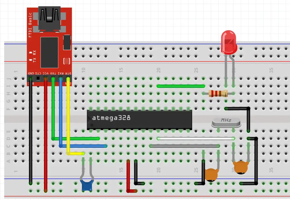
Connect USB to Serial/TTL adapter to the ATmega328p chip as shown in the figure below.

**Image source: programming ATmega328p
Uploading code
Uploading code to the microcontroller is an easy task to be done, after typing in your code, select the port to which your adapter is connected, follow by the board type “ATmega328p” and hit the upload button. The upload will finish in only a few seconds and the ATmega328 chip will be ready to use.
Using an Arduino board
The second way involves the use of an Arduino board in either of two similar methods:
- By replacing the microcontroller on the Arduino Uno with the one to be programmed
- By using any of the Arduino boards as an In-system programmer.
The first way is the easier way to upload code to the ATmega328p chip, as it involves just replacing the microcontroller present on the Uno, with the one we need to program. Just swap the microcontrollers and hit the upload button.
The second method way involves the use of the Arduino Uno as an In-system programmer. Like we burn the Bootloader in the chip, we can also use the Arduino ICSP header to upload code into the ATmega328 chip.
Required components
- Arduino Uno
- Breadboard
- USB to serial/TTL Adapter
- 16MHz crystal oscillator
- 22pf capacitors x2
- Jumper Wires
- 10k resistor
- 100 ohms resistor
- LED
Schematic
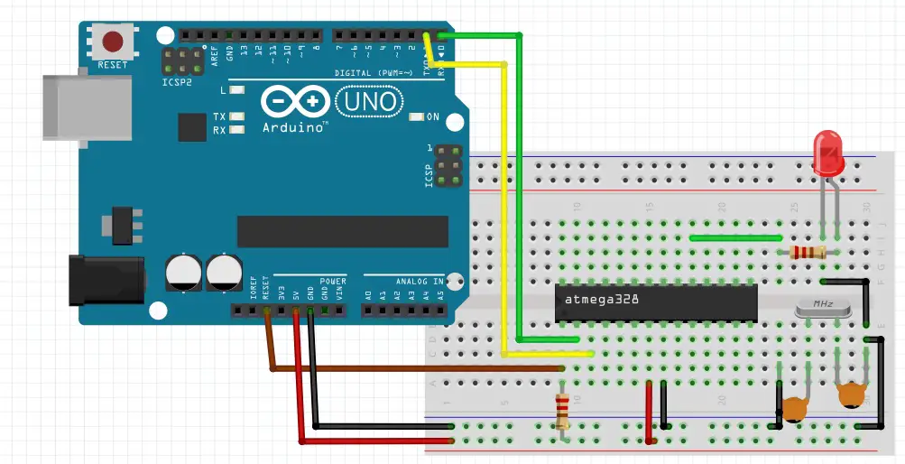
Connect the components as shown in the figure below.

Note: While using this approach, it is important to remove the microcontroller of the Arduino board to prevent interference.
Upload code
The code upload process is the same as already described. Select the code file that is to be uploaded on the ATmega328p, then select the board type (ATmega328p) and also the correct port, and click upload. The code will be uploaded to the microcontroller.
Projects and applications of ATmega328p:
There are many applications of Atmega328P in the real world.
The ATmega328P chip is compatible with a large set of program and system development tools such as C compilers, macro assemblers, program debugger/simulators, in-circuit emulators, and evaluation kits.
The fast PWM mode also provides a high-frequency PWM waveform generation. This allows it to be suited for power adjustment, rectification, and DAC (Digital to Analog Converter) applications. Some major applications for the chip are listed below:
- Industrial machinery controlling systems
- Solar-powered machinery and applications
- IoT based applications
- Power supply and charger-based applications
- Weather systems
- Wireless communication applications
- Security-based applications
- Medical & health-related projects & systems
- Automobile related applications
FAQs
How many ADC Pins are in ATmega328p?
It has a total of 6 ADC (analog to digital) Pins marked as (A0 – A5).
How many Pins are there in ATmega 328p?
It has a total of 28 pins that are used for various functions.
How much RAM does ATmega328p have?
The ATmega328p has 2KB of SRAM.
Read Similar Articles:
| Arduino UNO pinout and specifications in detail


