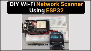
In this article, we demonstrated how to make a wireless network scanner using an ESP32 microcontroller and an OLED display. It searches for neighboring Wi-Fi networks, obtains their SSID and signal strength, and displays this data on the OLED display.
It can be used to optimize home networks, troubleshoot connectivity issues, and as a learning tool for Arduino programming and electronics.
Table of Contents
Watch the video tutorial below
Components required
- ESP32 microcontroller
- 0.96-inch I2C/IIC 4-pin OLED display module
Circuit diagram
The circuit diagram of the WiFi Network scanner is shown below.

Connections
There are a total of four pins on OLED. Connect them to ESP32 according to the table given below:
| OLED pin | ESP32 pin |
| VCC | 3V3 Pin |
| GND | GND of ESP32 |
| SDA | GPIO 21 |
| SCL | GPIO 22 |
We used a breadboard to connect the OLED with ESP32, as shown below.

Program
#include <Wire.h>
#include <Adafruit_SSD1306.h>
#include <WiFi.h>

#define SCREEN_WIDTH 128
#define SCREEN_HEIGHT 64
#define OLED_RESET -1
Adafruit_SSD1306 display(SCREEN_WIDTH, SCREEN_HEIGHT, &Wire, OLED_RESET);

void setup() {
  Serial.begin(115200);

  // Initialize the display
  if(!display.begin(SSD1306_SWITCHCAPVCC, 0x3C)) {
    Serial.println(F("SSD1306 allocation failed"));
    for(;;);
  }

  // Clear the display buffer
  display.clearDisplay();

  // Set text color, size, and position
  display.setTextColor(SSD1306_WHITE);
  display.setTextSize(1);
  display.setCursor(0, 0);

  // Connect to Wi-Fi
  WiFi.begin();
  while (WiFi.status() != WL_CONNECTED) {
    delay(1000);
    Serial.println("Connecting to WiFi...");
  }
  Serial.println("Connected to WiFi");

  // Print header on OLED display
  display.println("WiFi Networks:");
  display.display();
}

void loop() {
  int numNetworks = WiFi.scanNetworks();
  display.clearDisplay();

  if (numNetworks > 0) {
    for (int i = 0; i < numNetworks; i++) {
      // Get SSID and signal strength for each network
      String ssid = WiFi.SSID(i);
      int32_t rssi = WiFi.RSSI(i);

      // Print network details on OLED display
      display.print(ssid);
      display.setCursor(100, display.getCursorY());
      display.print(rssi);
      display.setCursor(0, display.getCursorY() + 10);
    }
  } else {
    display.println("No networks found");
  }

  display.display();
  delay(7000); // Delay for 5 seconds
}
Make sure to replace the SSID and PASSWORD with the credentials of your Wifi network
Program explanation
Include libraries:
#include <Wire.h>
#include <Adafruit_SSD1306.h>
#include <WiFi.h>
These lines include the libraries required for I2C connection (Wire), OLED display control (Adafruit_SSD1306), and Wi-Fi connectivity management (WiFi).
Define display parameters:
#define SCREEN_WIDTH 128
#define SCREEN_HEIGHT 64
#define OLED_RESET -1
These lines define constants for the OLED display’s width, height, and reset pin. The values are specific to the SSD1306 OLED display.
Initialize display:
Adafruit_SSD1306 display(SCREEN_WIDTH, SCREEN_HEIGHT, &Wire, OLED_RESET);
These lines are used for initializing the OLED display.
Setup function:
void setup() {
  Serial.begin(115200);

  // Initialize the display
  if (!display.begin(SSD1306_SWITCHCAPVCC, 0x3C)) {
    Serial.println(F("SSD1306 allocation failed"));
    for (;;);
  }

  // Clear the display buffer
  display.clearDisplay();

  // Set text color, size, and position
  display.setTextColor(SSD1306_WHITE);
  display.setTextSize(1);
  display.setCursor(0, 0);

  // Connect to Wi-Fi
  WiFi.begin();
  while (WiFi.status() != WL_CONNECTED) {
    delay(1000);
    Serial.println("Connecting to WiFi...");
  }
  Serial.println("Connected to WiFi");

  // Print header on OLED display
  display.println("WiFi Networks:");
  display.display();
}
In the setup() function:
- For debugging purposes, serial communication is started.
- The OLED display is initialized, and if it fails, an error message is printed and the program terminates.
- The display is cleared, and the text properties (color, size, and position) are specified.
- The code tries to connect to Wi-Fi and prints a message during the connection process.
- On the OLED display, a header (“WiFi Networks:”) is printed.
Loop function:
void loop() {
  int numNetworks = WiFi.scanNetworks();
  display.clearDisplay();

  if (numNetworks > 0) {
    for (int i = 0; i < numNetworks; i++) {
      // Get SSID and signal strength for each network
      String ssid = WiFi.SSID(i);
      int32_t rssi = WiFi.RSSI(i);

      // Print network details on OLED display
      display.print(ssid);
      display.setCursor(100, display.getCursorY());
      display.print(rssi);
      display.setCursor(0, display.getCursorY() + 10);
    }
  } else {
    display.println("No networks found");
  }

  display.display();
  delay(7000); // Delay for 5 seconds
}
In the loop() function:
- It searches for nearby Wi-Fi networks and records the number in numNetworks.
- The display is cleared.
- If there are available networks (numNetworks > 0), it iterates through them, collects their SSID and signal strength, and prints this information on the OLED display.
- If no networks have been detected, it displays the message “No networks found.”
- The display is updated, and there is a 5-second delay before the loop repeats.
Conclusion
In short, this project is a useful Wi-Fi network scanner using ESP32 and OLED display. It displays the nearby 2.4GHz Wi-Fi networks along with their signal strength. It’s not only useful for network analysis, but it’s also an excellent learning tool for Arduino enthusiasts.