Last updated on January 6th, 2026 at 11:10 am
If you are an Arduino beginner, willing to make awesome Arduino-based projects then you are in luck. These projects will not only give you a good understanding of Arduino but also teach you its applications.
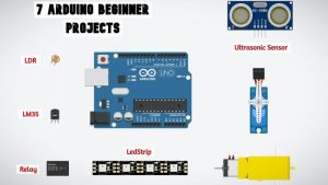
There are four different kinds of Arduino sensors used in some projects. Hence you will learn how to use IR, Ultrasonic, Temperature sensors, and Light-dependent Resistor(LDR).
Moreover, Two different Arduino projects made using LDR are included. You’ll learn how a small sensor like LDR can be used to make some cool projects.
The output devices are equally important as input devices. And it is essential to learn and know, which output device should be used in which application.
Output devices such as LEDs, DC motors, and Servo motors are explained and used in some of the projects. Finally, an Arduino -Home automation project made using an SPDT relay and LDR is also added to the list.
Having said that, let’s get started with our 7 awesome Arduino Projects for beginners.
Projects list
Watch the video given below for a detailed explanation of each project:
LED state control using IR sensor

Circuit diagram

Arduino program
void setup() {
  pinMode(7,INPUT);
  Serial.begin(9600);
  pinMode(13,OUTPUT);
}
void loop() {

Serial.print("IRSensorip  ");
Serial.println(digitalRead(7));
if(digitalRead(7)==0)
{
  digitalWrite(13,HIGH);
  }
 else{
    digitalWrite(13,LOW);
    }
}Distance measurement using Ultrasonic sensor

Circuit diagram

Arduino program
const int trig = 6;
const int echo = 7;
long totaltime;
int distance;
void setup() {

pinMode(trig, OUTPUT);
pinMode(echo, INPUT);
Serial.begin(9600);
}
void loop() {
digitalWrite(trig, LOW);
delayMicroseconds(2);
digitalWrite(trig, HIGH);
delayMicroseconds(10);
digitalWrite(trig, LOW);
totaltime = pulseIn(echo, HIGH);
distance= totaltime*0.034/2;
Serial.print("Distance: ");
Serial.println(distance);
}
Servo motor with Arduino

Circuit diagram

Arduino program
A) Driving servo motor to a predefined angle using Arduino servo library:
#include <Servo.h>
Servo servo1;
void setup() {

  servo1.attach(6);


}
void loop() {
  servo1.write(180);

}
B) Driving servo in a loop using the library
#include <Servo.h>
Servo servo1;
void setup() {

  servo1.attach(9);

}
void loop() {
  servo1.write(0);
  delay(1000);
  servo1.write(90);
  delay(1000);
  servo1.write(180);
  delay(1000);

  servo1.write(90);
  delay(1000);
}
C) Driving two servo motors
#include <Servo.h>
Servo servo1;
Servo servo2;
void setup() {

  servo1.attach(6);
  servo2.attach(9);

}
void loop() {
  servo1.write(0);
  delay(1000);
  servo2.write(0);
  delay(1000);
  servo1.write(90);
  delay(1000);
  servo2.write(90);
  delay(1000);
  servo1.write(180);
  delay(1000);
  servo2.write(180);
  delay(1000);
  servo1.write(90);
  delay(1000);
  servo2.write(90);
  delay(1000);
}
Light-controlled DC motor using LDR

Circuit diagram

Program
int x; // input of LDR
int y; // o/p Pwm value to be given to the base of the transistor to get reduced o/p voltage
void setup()
{
pinMode(A0,INPUT);
pinMode(6,OUTPUT);
Serial.begin(9600);
}
void loop()
{
x= analogRead(A0);// analog input from the pin A0 connected to LDR and POT. end
y= map(x,0,1023,0,255); // Mapping or converting the value bw
minimum to maximum analog value to the pwm value
analogWrite(6,y); // Writing this analog value to pin 6
which is connected to the base of the transistor to get reduced o/p voltage
Serial.print("LDR input ");
Serial.print(x);
Serial.print("\t");
Serial.print("O/P PWM value");
Serial.print(y);
Serial.println();
delay(1000);
}
Temperature-controlled fan using LM35

Circuit diagram

Arduino program
float Vout;
float Temp;
void setup() {

  Serial.begin(9600);
  pinMode(8,OUTPUT);
  pinMode(9,OUTPUT);
  pinMode(10,OUTPUT);
}
void loop() {
  Vout=analogRead(A0) ;
  Temp= (Vout*500)/1023 ;

  int PWMvalue=map(Temp,31,40,100,255);
  if(Temp>=30)
  {
    digitalWrite(8,HIGH);
    digitalWrite(9,LOW );

    analogWrite(10,PWMvalue);

   }
  else{
           analogWrite(10,0);
        }
  Serial.print("Temperature in Degree Celsius = ");
  Serial.print(Temp);
  Serial.print("\t");
  Serial.print("PWMValue = ");
  Serial.print(PWMvalue);
  Serial.print("\t");
  Serial.println();
  delay(1000);
}
Automated street light project

Circuit diagram

Code
int x; // input of LDR
void setup()
{
pinMode(10,INPUT);
pinMode(8,OUTPUT);
Serial.begin(9600);
}
void loop()
{
x= digitalRead(A0);// digital input from the pin 10 connected to LDR and POT. end
Serial.println(x);
delay(1000);
if(x==0){

  digitalWrite(8,HIGH);// if digital value is 0, i.e dark, bulb turns ON

  }

else{

  digitalWrite(8,LOW);// if digital value is 1, i.e daylight, bulb turns OFF

  }
}
DIY music-reactive lights

Circuit diagram

Code
# define SoundSensor 8
# define LedStrip 9
void Setup()
{
  pinMode(SoundSensor,INPUT);
  pinMode(LedStrip,OUTPUT);
  Serial.begin(9600);

  }
 Void loop()
 {
  int SensorValue = digitalRead(SoundSensor);
     if(SensorValue == 1)
     {
      digitalWrite(LedStrip,HIGH);
      delay(10);

      }
      else
     {
      digitalWrite(LedStrip,LOW);
      }
      Serial.println(SensorValue);
  }
Thanks for these 7 Great Projects online, but you put them on YouTube?
Or please let’s their Videos here.
Thanks
Hi Bob,
The link to the youtube video is given at the beginning of the article. You can see the working of all 7 projects in that video 🙂
Hi Sir,
It is a very usefull to me, Thank you so much. can I get such as live in youtube?
Thanks a lot .i want to be supported
Excellent 👌 and simple….