Last updated on November 17th, 2025 at 10:46 am
The Raspberry Pi 4 Model B was launched in June 2019. This model has the high-performance quad-core 64-bit Broadcom 2711, Cortex A72 processor clocked at 1.5GHz speed. This processor uses 20% less power and offers 90% greater performance than the previous model.
The other new features of the board are dual-display support up to 4k resolutions via a pair of micro-HDMI ports, hardware video decodes at up to 4Kp60, dual-channel 2.4/5.0GHz wireless LAN, true Gigabit Ethernet, two USB 3.0 ports, Bluetooth 5.0, and PoE capability (via a separate PoE HAT board).
Raspberry Pi 4 model comes in three different variants of 2 GB, 4 GB, and 8 GB LPDDR4 SDRAM.
Table of Contents
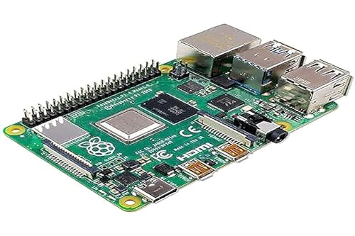
Board layout
The Raspberry Pi 4 board layout shows some major differences between the new RPI 4 and RPI 3B+: More memory, two micro HDMI ports that support 4K resolution, a USB C power port, etc.

CPU: It consists of a Broadcom BCM2711 chip which contains a 1.5GHz 64-bit quad-core ARM Cortex-A72 processor (using an ARMv8-architecture core).
GPU: Broadcom VideoCore VI @ 500 MHz was released in 2009. It is capable of BluRay quality video playback, H.265 (4Kp60 decode); H.264 (1080p60 decode, 1080p30 encode); OpenGL ES, 3.0 graphics.
RAM: It comes with 2GB, 4GB, and 8GB (depending on different versions) variants of LPDDR4 SDRAM.
USB port: It consists of two USB 3.0 and two USB 2.0 ports to connect it to an external keyboard, mouse, or other peripheral devices.
USB power port: It consists of a 5.1V, 3A USB type-C power port.
HDMI port: Two micro HDMI ports capable of supporting up to 4k@60HZ resolution.
Ethernet port: It comes with a true Gigabit Ethernet capable of sending Ethernet frames at a rate of one gigabit per second (1 billion bits per second).
Composite video output: Both the audio output socket and the video composite socket reside in a single 4-pole 3.5mm socket.
SD card slot: A micro-SD card slot is used for booting up the operating system and storage purposes.

Note: The SD card slot is given at the back of the Raspberry Pi 4 board
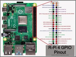
Raspberry Pi 4 GPIO pinout
Raspberry Pi 4 has 40 pins: 26 GPIO pins, two 5V pins, two 3V3 pins, and 7 ground pins.
These pins are capable of generating PWM output and the board supports SPI, I2C, and UART serial communication protocols.
A standard interface for connecting a single-board computer or microprocessor to other devices is through General-Purpose Input/Output pins.

Have a close look at the GPIO header.

The table below describes these pins.
| Pin Type | GPIO Pins |
| PWM pins (Hardware) | GPIO12, 13, 18, 19 |
| SPI pins | SPI0: GPIO9 (MISO), 10 (MOSI), 11 (SCLK), 8 (CE0), 7 (CE1) SPI1: GPIO19 (MISO), 20 (MOSI), 21 (SCLK), 18 (CE0), 17 (CE1), 16 (CE2) |
| I2C pins | Data: (GPIO2), Clock: (GPIO3) EEPROM Data: (GPIO0), EEPROM Clock: (GPIO1) |
| UART pins | TX: (GPIO14) RX: (GPIO15) |
Since GPIO pins do not have any specific function, these pins can be customized using the software.
Power pins
The Raspberry Pi 4 model B board consists of two 5V pins, two 3V3 pins, and 7 ground pins (0V).

5V: The 5v pin outputs the 5 volts coming from the USB Type-C port.
3.3V: The 3v pin is used to provide a stable 3.3v supply to external components.
GND: The ground pin is commonly referred to as GND.
Input/Output pins
A pin that can be set as an input or output and is controlled in run time is called a GPIO pin.
A GPIO pin set as input allows the signal transmitted by any external device (connected to this pin) to be received by the Raspberry Pi.
Input voltage between 1.8V and 3.3V is read as HIGH by the Raspberry pi. When the input voltage is lower than 1.8V, it is read as LOW.
Note: Do not connect an external device with an output voltage above 3.3V to any of the GPIO pins, or else it will fry your Raspberry Pi board.
A GPIO pin set as output delivers HIGH/3.3V or LOW/0V.
Apart from Input/Output, the GPIO pins can also perform a variety of other functions like PWM. Some of these functions/pins are:
PWM (pulse-width modulation) pins
PWM stands for “Pulse Width Modulation”. It means that an analog value is being modulated on a digital signal.
Software PWM is available on all pins.
Hardware PWM is available on these pins only: GPIO12, 13, 18 and 19. There are only two channels: channel 1(12,18) and channel 2(13,19). So you can generate only two different PWM signals at the same time.
SPI pins
SPI (Serial Peripheral Interface) is a type of serial communication protocol. It is used by the Raspberry Pi for master-slave communication to quickly communicate between one or more peripheral devices.

SPI0: GPIO9 (MISO), 10 (MOSI), 11 (SCLK), 8 (CE0), 7 (CE1)
SPI1: GPIO19 (MISO), 20 (MOSI), 21 (SCLK), 18 (CE0), 17 (CE1), 16 (CE2)
The data is synchronized using a clock (SCLK at GPIO11) from the master (RPi).
The Pi sends this data to an SPI device using MOSI (Master Out Slave In) pin. And when the SPI device needs to communicate back to the Raspberry Pi, it sends the data back through the MISO (Master In Slave Out) pin.
5 pins are required for SPI communication:
GND: Connect the GND pin from all the slave components and the Raspberry Pi 4 board together.
SCLK: Clock for SPI communication.
MOSI: It stands for Master Out Slave In. This pin is used to send data from the master to a slave.
MISO: It stands for Master In Slave Out. This pin is used to receive data from a slave to the master.
CE: It stands for Chip Enable. We need to connect one CE pin per slave (or peripheral devices) in our circuit. By default, we have two CE pins but we can configure more CE pins from the other available GPIO pins.
I2C pins

I2C pins on the Raspberry Pi board are used to communicate with peripheral devices that are compatible with Inter-Integrated Circuit (a low-speed two-wire serial communication protocol).
This serial communication protocol requires master-slave roles between both, the board and the peripheral devices.
I2C protocol requires two connections: SDA (Serial Data) and SCL (Serial Clock). They work by transmitting data using the SDA connection, and the speed of data transfer is controlled via the SCLK pin.
Data: (GPIO2), Clock (GPIO3)
EEPROM Data: (GPIO0), EEPROM Clock (GPIO1)
UART pins
The UART (Universal Asynchronous Receiver / Transmitter) is an asynchronous protocol that provides a way to communicate between two microcontrollers or devices.
TX pin transmits the serial data to the RX pin of another device and RX pin receives the serial data coming from TX pin of the other device.
TX: GPIO14
RX: GPIO15
Specifications
The table given below gives the complete specifications of the Raspberry Pi 4.
| Specs | Detail |
| Processor | Broadcom BCM2711 chip consist of Quad-core Cortex-A72 (ARM v8) 64-bit SoC @ 1.5GHz |
| Memory | 2GB, 4GB, and 8GB of LPDDR4 SDRAM (depending on the version of the board) |
| Wireless module | Dual-channel 2.4/5.0 GHz IEEE 802.11ac wireless, Bluetooth 5.0, BLE |
| Connectivity | 2 x USB 3.0 ports 2 x USB 2.0 ports 2 x micro-HDMI ports(support up to 4kp60 resolution) 2-lane MIPI DSI display port 2-lane MIPI CSI camera port |
| Audio/video | 4-pole stereo audio and composite video port |
| Multimedia | 265 (4k@60 decode), H264 (1080@60 decode and 1080@30 encode) |
| Input power | Operating temperature: 0 – 50 °C |
| Operating Temperature | OpenGL ES 3.0 graphics Micro-SD card slot for loading the operating system and data storage Power over Ethernet (PoE) enabled(requires PoE HAT board) |
| Others | OpenGL ES 3.0 graphics Micro-SD card slot for loading operating system and data storage Power over Ethernet (PoE) enabled(requires PoE HAT board) |
Schematic (official)
**To download the Raspberry Pi 4 schematic, click here.

Physical dimensions
The dimensions of the Raspberry Pi 4 are 85 mm in length and 56 mm in width.

Ways to program the Raspberry Pi 4 board
You can control the Raspberry Pi 4 GPIO pins using many programming languages. Some of the popular languages along with learning material are given below:
- Using python
- With C/C++ using standard kernel interface via libgpiod
- With C/C++ using 3rd party library pigpio
- Using Scratch 1.4
- Using Scratch 2
- Using Processing3
Prefer books? Read this article on Best Raspberry Pi Books for beginners
Where to buy Rpi 4 and its accessories?
You can get the original Raspberry Pi 4 board from different stores. But if you want to get it from Amazon, we recommend the following sellers:

FAQs
Is PI 64-bit OS compatible with Pi 4?
Since the Pi 4 has a 64-bit architecture, the board is compatible with the Pi 64-bit OS. The official version of the Pi 64-bit OS was launched recently by the RPI foundation and can be installed from their website.
How many GPIOs does Raspberry Pi 4 have?
R-Pi has a 40-pin header out of which 28 pins are GPIO pins.
Can you power a Raspberry Pi 4 with GPIO pins?
No, you can not power a R-Pi 4 using any of the 28 GPIO pins. But, it’s possible to power it using the 5V and GND pins of the GPIO header.
What is the purpose of GPIO in Raspberry Pi 4?
The GPIO pins are used to connect external components like sensors, actuators, displays, etc. with the SoC.
I want to know how long are the GPIO pins, the physical length.
Yeah are 5mm
They are 5mm
I am wondering if there is a way to copy the all of the circuit and create a clone of raspberry pi. I do not need a couple of futures of it so I want to remove them and I want to build my own version. PLease help me.
Hi,
What features you would like to have in your clone? And I am pretty sure you can get a board with the same features at a reasonable price.
Hey,
thank you for the article.
I found one tiny mistake. Once you said RPi4 has a BCM2711 with Cortex-A53 and down the page you said its an BCM2711 with Cortex-A72. Of Course Cortex-A72 is right.
Hey,
Thank you for telling us the mistake. We appreciate it.
The error has been resolved now.