Last updated on February 22nd, 2024 at 12:11 pm
In this post, I will show you how to change the PWM frequency of Arduino Nano. PWM or pulse width modulation is a method of reducing the output voltage by switching the input voltage ON/OFF at a very high frequency. Here reducing means getting the average voltage value at the output.
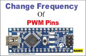
Arduino Nano PWM pins
There are a total of 6 PWM pins available on the board that can supply such PWM voltage output. These pins are numbered as 3, 5,6,9,10, and 11. On Arduino boards, PWM pins are either identified by the “~” sign printed next to the pin or “-” marked above the pin name.

To get the PWM output, the “analogWrite(PWM pin, PWM value)” command is used. The PWM value varies between 0 and 255. PWM value 255 means 5 Volts at the output and 0 means 0 volts. Any PWM value between 0 and 255 gives the voltage between 0 and 5 volts at the output.
As mentioned above, the PWM output is achieved by switching the input voltage(5V) at a certain frequency. Depending on your application/project this frequency may vary. But there is a certain default frequency with which PWM output is generated out of the PWM pins of Arduino Nano.
And this default frequency can be changed to a value as high as 65Khz for some pins and as low as 30Hz for other pins. This is done by adding a one-line command in the code section without altering the shape of the PWM wave or major attenuation.
| Looking for Arduino UNO PWM frequency change?
|
Default Arduino Nano PWM frequency
On Arduino Nano, there are a total of 6 PWM pins available. These pins are numbered as 3, 5,6,9,10, and 11. The default PWM frequency for all pins is 490 Hz, except pins 4 and 13 whose default frequency is 980Hz.
Default PWM frequency from D3, D9, D10, and D11:

490.20 Hz (The DEFAULT)

Default PWM frequency for D5 & D6:

976.56 Hz (The DEFAULT)
Now, these frequencies are optimum for low-frequency applications like fading an LED. But these default frequencies are not suitable for High-frequency circuits like buck/boost converters and S.M.P.S.
So to achieve frequency lower or higher than the default frequency on PWM pins, the one-line command that we can use before initializing the PWM pin as output is given below:
Commands for changing Arduino Nano PWM pins frequency
| Code for Available PWM frequency on D3 & D11:
TCCR2B = TCCR2B & B11111000 | B00000001; // for PWM frequency of 31372.55 Hz TCCR2B = TCCR2B & B11111000 | B00000010; // for PWM frequency of 3921.16 Hz TCCR2B = TCCR2B & B11111000 | B00000011; // for PWM frequency of 980.39 Hz TCCR2B = TCCR2B & B11111000 | B00000100; // for PWM frequency of 490.20 Hz (The DEFAULT) TCCR2B = TCCR2B & B11111000 | B00000101; // for PWM frequency of 245.10 Hz TCCR2B = TCCR2B & B11111000 | B00000110; // for PWM frequency of 122.55 Hz TCCR2B = TCCR2B & B11111000 | B00000111; // for PWM frequency of 30.64 Hz |
| Code for Available PWM frequency on D5 & D6:
TCCR0B = TCCR0B & B11111000 | B00000001; // for PWM frequency of 62500.00 Hz TCCR0B = TCCR0B & B11111000 | B00000010; // for PWM frequency of 7812.50 Hz TCCR0B = TCCR0B & B11111000 | B00000011; // for PWM frequency of 976.56 Hz (The DEFAULT) TCCR0B = TCCR0B & B11111000 | B00000100; // for PWM frequency of 244.14 Hz TCCR0B = TCCR0B & B11111000 | B00000101; // for PWM frequency of 61.04 Hz |
| Code for Available PWM frequency on D9 & D10:
TCCR1B = TCCR1B & B11111000 | B00000001; // for PWM frequency of 31372.55 Hz TCCR1B = TCCR1B & B11111000 | B00000010; // for PWM frequency of 3921.16 Hz TCCR1B = TCCR1B & B11111000 | B00000011; // for PWM frequency of 490.20 Hz (The DEFAULT) TCCR1B = TCCR1B & B11111000 | B00000100; // for PWM frequency of 122.55 Hz TCCR1B = TCCR1B & B11111000 | B00000101; // for PWM frequency of 30.64 Hz |
| Looking for Arduino Mega PWM frequency change?
|
How to change the Arduino Nano PWM frequency in Proteus
To show you how the frequency changes on applying the above commands, a circuit is simulated in Proteus for Arduino Nano. There are two Arduino Nano selected for this purpose and PWM pin 3 is used. Nano 1 generates the default frequency of 490 Hz(without command) and the other one generates the PWM frequency of 3921 Hz. The output of both the Arduino Nano is then given to the oscilloscope.
Check out: How to add Arduino Library to Proteus and Simulate Arduino Projects
1. Two Arduino are selected and placed on the Front sheet.
2. Digital Pin 3 ( PWM pin) of each Arduino is connected to an oscilloscope
3. Two separate programs are written for each Arduino and then the hex file is uploaded separately:
Program A for Nano1 – Default frequency on Pin 3 :
void setup() {
pinMode(3,OUTPUT);
}
void loop() {
analogWrite(3,155);
}
Program B for Nano2 – Changed frequency on Pin 3 :
void setup() {
TCCR2B = TCCR2B & B11111000 | B00000001; // for PWM frequency of 3921.16 Hz
pinMode(3,OUTPUT);
}
void loop() {
analogWrite(3,155);
}
5. Run Simulation


6. It can be clearly seen on the oscilloscope that frequency is increased to a very high value when this command is used in void setup() :
TCCR2B = TCCR2B & B11111000 | B00000010; // for PWM frequency of 3921.16 Hz
Read Similar Articles:
| How to add Arduino Library to Proteus and Simulate Arduino Projects
| How to Add Microphone library to Proteus and generate audio waveforms
| How to Add And Simulate Ultrasonic Sensor Library in Proteus
Hello sir please i want to know whether those can be applied to teensy board
Hi david,
Teensy board doesn’t have an atmega chip at its core. It runs on Arm processor I guess. So its not possible to use the code given here on Teensy.
Thanks for these single line commands.
Where does the figure of 3921.16 Hz come from? Is that what your oscilloscope measured? I would have expected 3906.25 Hz.
Very helpful information; thanks!