Last updated on March 14th, 2024 at 01:33 pm
The Raspberry Pi 1 was one of the first single-chip computers developed in the UK by the Raspberry Pi Foundation. It is a small, efficient, cheap computer that can be plugged into the TV and a keyboard, and can be used as a regular desktop.
The board consists of a Broadcom BCM2835 SoC, which includes an ARM1176JZF-S 700 MHz processor, a VideoCore IV graphical processor, and 512 MB of RAM. The board does not include a built-in HDD or SSD.
Instead of that, it uses an SD card for booting and long-term storage and is intended to run Linux kernel-based operating systems. Raspberry Pi 1 GPIO Pinout with functions, schematic, and specs are given in detail below.
Table of Contents
Board layout

CPU/Processor: It consists of a Broadcom BCM2835 chip which contains an ARM1176JZFS (ARM11 using an ARMv6-architecture core) with a floating point unit, running at 700Mhz.
GPU: Broadcom VideoCore IV @ 250 MHz was released in 2009. It is capable of BluRay quality video playback, using H.264 at 40Mb/s, it has a fast 3D core accessed using the supplied OpenGL ES2.0 and OpenVG libraries.
RAM: It consists of 512 MB LPDDR2 SDRAM.
USB port: It consists of 2 USB ports to connect it to an external keyboard, mouse, or other peripheral devices.
Micro USB power port: 5V DC Micro USB power port capable of supplying at least 700mA.
HDMI port: A HDMI port to connect the board to the monitor.
Ethernet Port: A new RJ-45 Ethernet port.
Composite video output: It consists of an RCA jack for composite video purposes.
Audio output: It has a 3.5mm audio jack for analog audio output.
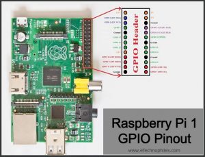
Raspberry Pi 1 GPIO pinout

GPIO stands for General Purpose Input Output pins these pins are used to connect the Raspberry pi board to external input/output devices. This model B consists of a 26-pin GPIO.
A standard interface for connecting a single-board computer or microprocessor to other devices is through General-Purpose Input/Output (GPIO) pins, these pins don’t have a specific function these pins can be customized using the software.
Power pins
The Raspberry pi 1 model B board consists of two 5V pins, two 3V3 pins, and 5 ground pins (0V), which are unconfigurable.
5V: The 5v pins are used to directly deliver the 5v supply coming from the mains adaptor. This pin can use to power up the Raspberry Pi, and it can also use to power up other 5v devices.
3.3V: The 3v pin is used to provide a stable 3.3v supply to external components and also to test LEDs.
GND: Ground is commonly referred to as GND.
Input/Output pins
A GPIO pin set as Input reads the signal received by the Raspberry Pi, sent by the device connected to this pin. Any voltage between 1.8V and 3.3V is read as HIGH and voltage lower than 1.8V as LOW by the Raspberry Pi.
Note: Do not connect a device with an input voltage above 3.3V to any of the GPIO pins, or else it will fry the Raspberry Pi.
A GPIO pin set as an output pin sends the voltage signal as high (3.3V) or low (0V). When this pin is set to HIGH, the voltage at the output is 3.3V and when set to LOW, the output voltage is 0V.
Along with the simple function of input and output pins, the GPIO pins can also perform a variety of specific functions. Some specific pins are:
PWM pins
The board consists of only one PWM pin, the PWM pin available on the GPIO header is shared with the Audio system which means that we cannot use the PWM output and play audio through the 3.5mm jack at the same time.
- PWM pins: GPIO18
I2C pins
I2C in the Raspberry Pi board is used to communicate with peripheral devices that are compatible with Inter-Integrated Circuit (a low-speed two-wire serial communication protocol). This communication standard requires master-slave roles between both the board and the peripheral devices.
I2C has two connections: SDA (Serial Data) and SCL (Serial Clock). They work by transmitting data using the SDA connection, and the speed of data transfer is controlled via the SCL pin.
- Data: (GPIO2), Clock (GPIO3)
SPI pins
SPI (Serial Peripheral Interface) is another protocol used by the Raspberry Pi for master-slave communication to quickly communicate between one or more peripheral devices.
Data is synchronized using a clock (SCLK at GPIO11) from the master (RPi) and the data is sent from the Pi to our SPI device using the MOSI (Master Out Slave In) pin.
If the SPI device needs to communicate back to Raspberry Pi, then it will send data back using the MISO (Master In Slave Out) pin. There are 5 SPI pins on the board:
- GND: Connect all GND pins from all the slave components and the Raspberry Pi 3 board together.
- SCLK: Clock of the SPI. Connect all SCLK pins.
- MOSI: It stands for Master Out Slave In. This pin is used to send data from the master to a slave.
- MISO: It stands for Master In Slave Out. This pin is used to receive data from a slave to the master.
- CE: It stands for Chip Enable. We need to connect one CE pin per slave (or peripheral devices) in our circuit. By default, we have two CE pins but we can configure more CE pins from the other available GPIO pins.
SPI pins:
- SPI0: GPIO9 (MISO), GPIO10 (MOSI), GPIO11 (SCLK), GPIO8 (CE0), GPIO7 (CE1)
Serial or UART pins
Serial communication or the UART (Universal Asynchronous Receiver / Transmitter) is an asynchronous protocol that provides a way to communicate between two microcontrollers or computers. TX pin is used to transmit the serial data and RX pin is used to receive serial data coming from a different serial device.
- TX (GPIO14)
- RX (GPIO15)
Specifications
- 700 MHz ARM11 processor
- 512 MB of RAM
- GPU: Broadcom VideoCore IV@250MHz
- Ethernet port
- Two USB ports
- Two video output options: HDMI or composite
- 3.5 mm audio output jack
- 26-pin GPIO header with 0.1″-spaced male pins that are compatible with our 2×13 stackable female headers and the female ends of our premium jumper wires.
- Size: 3.35″ × 2.2″ × 0.8″
- Weight: 40g
**You can find more details of the board, here.
Ways to program the Raspberry PI 1 Board
You can control the GPIO of Raspberry Pi 1 using many programming languages. Some of the popular languages along with learning material is given below:
- Using Python
- Using standard kernel interface via libgpiod
- With C/C++ using 3rd party library pigpio
- Using Scratch 1.4
- Using Scratch 2
- Using Processing3
FAQs
Is Raspberry Pi 1 64-bit?
No, Raspberry Pi 1 has a 32-bit architecture set.
Is Raspberry Pi 1 ARM-based?
Yes, the Pi 1 consists of a 700 MHz ARM11 processor.
Can Raspberry Pi 1 run Windows?
No, the Pi 1 can’t run Windows.
Read Similar Articles:
| Raspberry Pi 3 Model B Pinout and Specs in detail
| Raspberry Pi Zero GPIO pinout and specifications in detail