Last updated on March 26th, 2024 at 04:29 pm
The Arduino Mega 2560 is an open-source development board that is developed by the Arduino company. It is based on the Microchip ATmega2560P by Atmel. The Atmega2560P is an 8-bit microcontroller that comes with a built-in bootloader, which makes it very convenient to flash the board with our code.
Like all Arduino boards, we can program the software running on the board using a language derived from C and C++. The easiest development environment is the Arduino IDE.
Atmega 2560P-based Arduino Mega pinout and specifications are given in detail in this post.
Table of Contents
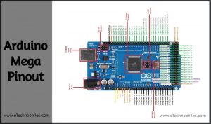
Arduino Mega pinout(detailed board layout)
Arduino Mega 2560 has 54 digital input/output pins, where 16 pins are analog inputs, 14 are PWM pins, and 6 are hardware serial ports (UARTs). It has a crystal oscillator-16 MHz, a power jack, an ICSP header, a USB-B port, and a RESET button.

Voltage Regulator-The voltage regulator converts the input voltage to 5V . The primary use of a voltage regulator is to control the voltage level in the Arduino board. Even if there are any changes in the input voltage of the regulator, the output voltage is constant and steady.
ATmega2560P: It is an 8-bit AVR RISC (Reduced Instruction Set Computer) based microcontroller that executes powerful instructions in a single clock cycle. This allows it to effectively find a balance between power consumption and processing speed.
Crystal Oscillator- The Crystal oscillator has a frequency of 16MHz, which provides the clock signal to the microcontroller. It provides the basic timing and control to the board.
RESET Button-It is used to Reset the board, recommended to press it each time we flash some code to the board.
Are you a beginner? Can't decide which book to read? Check out this article on Best Arduino Books for beginners
How to power the Arduino Mega 2560?
There are three ways to power the Arduino Mega Board:
Barrel Jack – The Barrel jack, or 7-12V DC Power Jack can be used to power our Arduino board. The barrel jack is usually connected to an adapter. The board can be powered by an adapter that ranges between 5-20 volts but the manufacturer recommends keeping it between 7-12 volts.
Note: Above 12 volts, the board may overheat and voltage below 7 volts might not be sufficient to power the board.
Note: Above 12 volts, the board may overheat and voltage below 7 volts might not be sufficient to power the board.USB B-port-The USB Interface is used to plug in the USB cable. This port can be used to power the device from the 5V supply and allows us to connect the board to the computer. The program is uploaded to the board serially from the computer through the USB cable.
Vin–It is the modulated DC supply voltage, which is used to regulate the ICs used in the connection. It is also called the primary voltage for ICs present on the Arduino board. The Vcc voltage value can be negative or positive to the GND pin.
I2C Pins
It is the two-wire serial communication protocol. It stands for Inter-Integrated Circuits. The I2C uses two lines to send and receive data: a serial clock pin (SCL) and a serial data (SDA) (SDA) pin.
- SCL-It stands for Serial Clock. It is defined as the line that transfers the clock data. It is used to synchronize the shift of data between the two devices. The Serial Clock is generated by the master device.
- SDA-It stands for Serial Data. It is defined as the line used by the slave and master to send and receive data. That’s why it is called a data line, while SCL is called a clock line.
SPI Pins
It stands for Serial Peripheral Interface. The PINs 50, 51, 52, and 53 are used as SPI pins. They are used by the microcontrollers to communicate with one or more peripheral devices quickly. There are three common lines to all the peripheral devices:
- SCK-It stands for Serial Clock. These are the clock pulses, that are used to synchronize the transfer of data.
- MISO-It stands for Master Input/ Slave Output. This data line in the MISO pin is used to send the data to the master.
- MOSI-It stands for Master Output/ Slave Input. This line is used for sending data to the peripherals.
And one common line:
- SS-It stands for Slave Select. This line is used by the master. It acts as the enable line. When a device’s Slave Select pin value is LOW, it can communicate with the master. When it’s value HIGH, it ignores the master. This allows us to have multiple SPI peripheral devices sharing the same MISO, MOSI, and CLK lines
UART pins
UART stands for Universal Asynchronous Receiver and Transmitter. It enables the Arduino to communicate with serial devices. There are 4 UART in Arduino Mega:
- Pin 0 – RXD0, pin 1 – TXD0
- Pin 19 – RXD1, pin 18 – TXD1
- Pin 17 – RXD2, pin 16 – TXD2
- Pin 15 – RXD3, pin 14 – TXD3
This pin is used for serial UART communication with pc or other serial devices for purpose of data sharing and logging. It is used with serial.Begin() function to set baud rate setting and start communication with serial.Println() function to print an array of char on another device output.
External Interrupts – The external interrupts can be formed by using 6-pins like interrupt 0(0), interrupt 1(3), interrupt 2(21), interrupt 3(20), interrupt 4(19), interrupt 5(18). These pins can be used to trigger an interrupt on a low value, a rising or falling edge, or a change in value.
What is an ICSP Header?

It stands for In-Circuit Serial Programming. We can use these pins to program the Arduino board’s firmware. The firmware changes with the new functionalities are sent to the microcontroller with the help of the ICSP header.
The ICSP header consists of 6 pins.
Analog pins
The Arduino Mega consists of 16 analog pins, which use ADC (Analog to Digital converter). These pins can serve as analog inputs but can also function as digital inputs or digital outputs.
These pins accept inputs in the form of Analog signals and return values that range between 0 and 1023 (that’s because the Arduino Mega has a 10-bit Analog to Digital converter or 210 resolution).
An Analog to digital converter works in three stages: sampling, quantization, and digitization. Because the Arduino operates on a 0–5 volts range the step size of the device is 5/1023=0.00488volts or 4.88mV.
Thus, we can interpret a 4.88 mV input as 1, 9.77 mV as 2, and so on until 5 V = 1023. Anything below 4.88 mV is considered 0 and above 4.99 V as 1023.

Digital pins
Arduino Mega 2560 has 54 digital I/O pins. All the Pins between 0 to 53 are digital input/output pins.
The Arduino digital pins can read only two states: when there is a voltage signal and when there is no signal. This kind of input is usually called digital (or binary) and these states are referred to as HIGH and LOW or 1 and 0.
LED (13): In the board, there is a built-in LED connected to digital pin 13. When this pin is HIGH or 1, the LED is switched on, when the pin is LOW or 0, it’s switched off.
PWM pins
There are 15 pins from the set of digital pins that are PWM (Pulse Width Modulation) pins. Starting from digital pin 2 to digital pin 13 and pin 44, 45, and 46 are PWM pins.

Every one of these digital pins can generate a Pulse Width Modulation signal of 23-bit resolution. We can generate the PWM signal using the analogWrite() function.
Other pins
GND (Ground pins): There are 7 ground pins available on the board.
RESET – resets the Arduino board.
I/O Reference Voltage (IOREF) – This pin is the input/output reference. It provides the voltage reference at which the microcontroller is currently operating. Sending a signal to this pin does nothing.
AREF: AREF means Analogue Reference. It is the reference voltage against which all other analog voltages (analog inputs) are measured.
3.3V and 5V: These pins provide regulated 5V and 3.3V respectively to the external components connected to the board.
Specifications
Given below are the technical specifications of Arduino Mega 2560:
| Microcontroller | ATmega2560 |
| Operating Voltage | 5 V |
| Power supply | 7 V – 12 V |
| Current consumption | 50 mA – 200 mA |
| Current consumption Deep Sleep | 500 µA |
| Digital I/O Pins | 54 |
| Digital I/O Pins with PWM | 15 |
| Analog Input Pins | 16 |
| DC Current per I/O Pin | 40 mA |
| DC Current for 3.3V Pin | 50 mA |
| Flash Memory | 256 KB |
| SRAM | 8 KB |
| EEPROM | 4096 bytes |
| Clock Speed | 16 MHz |
| Length | 102 mm |
| Width | 53 mm |
| Power jack | yes |
| USB connection | yes |
Arduino Mega schematic(official)
To download Arduino Mega Schematic, click here.


Where to Buy Arduino Mega?
You can get the original Arduino Mega board from different stores. But if you want to get it from Amazon, we recommend the following sellers:
![Arduino Mega 2560 REV3 [A000067] - ATmega2560, 16MHz, 54 Digital I/O, 16 Analog Inputs, 256KB Flash, USB, Compatible with Arduino IDE for Advanced Projects](https://m.media-amazon.com/images/I/51SQnHx-AmS.jpg)

FAQs
Is Arduino Mega 2560 8-bit?
The Arduino Mega 2560 board is based on the Atmega2560 microcontroller, which is indeed an 8-bit microcontroller. Therefore, yes, the Arduino Mega 2560 utilizes an 8-bit microcontroller.
What is 2560 in Arduino Mega?
The “2560” in Arduino Mega 2560 is the model number of the microcontroller used on the board.
Can Arduino run 64-bit?
No, Arduino boards typically use 8-bit or 32-bit microcontrollers. They do not support 64-bit architectures.
I am searching for specifics for the Arduino Mega.
Hello. Thank you for your detail. One issue is that your diagram of the ICSP layout is rotated 180 degrees relative to the photo next to it. Pin 1 (MOSI) should be on the upper-left. Thank you.