Last updated on March 26th, 2024 at 04:20 pm
The Arduino Leonardo is a microcontroller board based on the ATmega32u4 microchip. The Atmega32u4 comes with a built-in bootloader, which makes it convenient to flash the Arduino board with our code.
It consists of a total of 20 digital I/O pins (of which 7 can be used as PWM outputs and 12 as analog inputs), a power jack, a micro USB port, a 16 MHz crystal oscillator, an ICSP header, and a reset button. Atmega32u4-based Arduino Leonardo pinout and specifications are given in detail in this post.
Table of Contents
Specifications
Given below are the technical specifications of the Arduino Leonardo.
| Microcontroller | ATmega32u4 |
| Operating Voltage | 5V |
| Input Voltage (Recommended) | 7-12V |
| Input Voltage (limits) | 6-20V |
| Digital I/O Pins | 20 |
| PWM Channels | 7 |
| Analog Input Channels | 12 |
| DC Current per I/O Pin | 40 mA |
| DC Current for 3.3V Pin | 50 mA |
| Flash Memory | 32 KB (of which 4 KB is taken by bootloader) |
| SRAM | 2.5 KB (ATmega32u4) |
| EEPROM | 1 KB (ATmega32u4) |
| Clock Speed | 16 MHz |
| Length | 68.6 mm |
| Width | 53.3 mm |
| Weight | 20 g |
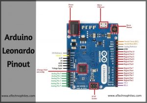
Arduino leonardo pinout

ATmega32u4 Microchip: The ATmega32u4 is a high-performance, low power AVR 8-bit microchip. It has 32 KB (of which 4 KB is used by the bootloader), 2.5 KB of SRAM, and 1 KB of EEPROM.
Crystal Oscillator: The Crystal oscillator inside the board has a frequency of 16MHz, which generates the clock signal in the microcontroller. Its basic function is to provide the basic timing and control to the board.
How to power Arduino Leonardo pinout?
Barrel Jack – The Barrel jack, or 7-12V DC Power Jack can be used to power your Arduino board. The barrel jack is connected to an adapter. The board is compatible with any adapter that power ranges between 5-20 volts but the manufacturer recommends keeping it between 7-12 volts.
Note: Above 12 volts, the board may overheat and voltage below 7 volts might not be sufficient to power the board.
Micro USB Port – The Micro USB is smaller than the standard Mini USB port and it is much flatter and slightly taper than the micro USB. It allows us to bridge the connection between the board and the computer. It is very important for the programming of the Arduino Leonardo board.
Vin: It is the input voltage pin that is connected to the external power supply to power up the Arduino board. If the voltage is supplied via the power jack, this pin can be used as a power pin.
Analog Input
The Leonardo consists of 12 analog inputs, labeled from A0 to A11, all of these pins can also be used as digital I/O pins. Each of these analog pins has an inbuilt ADC of resolution of 210 bits (so it will give 1024 values).

Digital I/O pins
20 digital I/O pins on the Leonardo can be used as an input or output. They operate at 5 volts. The Arduino Leonardo digital pins can read only two states: when there is a voltage signal present and when it is absent. This kind of input is usually known as digital (or binary) and these states are referred to as HIGH and LOW or 1 and 0.
PWM pins
There are six pins from the set of digital pins that are PWM (Pulse Width Modulation) pins which are numbered as 3, 5, 6, 9, 10, 11, and 13. Provide 8-bit PWM output with the analogWrite() function.
UART pins

These pins are used for serial communication, 0 (RX) to receive the data, and 1 (TX) to transmit (TX) TTL serial data using the ATmega32U4 hardware serial capability.
ICSP
It stands for In-Circuit Serial Programming. These pins are used to program the Arduino Leonardo board’s firmware. The new firmware changes with the new capabilities are sent in through the microcontroller with the help of this ICSP header.
The ICSP header consists of 6 pins.
Two-wire interface (TWI)/I2C

It is the two-wire serial communication protocol. It stands for Inter-Integrated Circuits. The I2C uses two lines to send and transmit data: a serial clock (SCL) pin and a serial data (SDA) pin.
- SCL-It stands for Serial Clock. It is defined as the pin that transmits the clock data. It is used to synchronize the sending of data between the two devices. The Serial Clock is provided by the master device.
- SDA-It stands for Serial Data. It is defined as the pin used by both the slave and master to send and receive the data in between. That’s why it is also known as a data line, while SCL is known as a clock line.
External interrupt pins

There are 5 external interrupt pins in the board: 3 (interrupt 0), 2 (interrupt 1), 0 (interrupt 2), 1 (interrupt 3) and 7 (interrupt 4). These pins can be configured such that if any of the following changes occur: on a low value, a rising or falling edge, or a change in value.
SPI pins
It stands for Serial Peripheral Interface. These pins are used by the microcontrollers to communicate with one or more peripheral devices efficiently. Unlike Arduino UNO the SPI pins in Leonardo board are present on the ICSP header, these pins support SPI communication using the SPI library. This means that even if we have a shield that uses SPI communication, but does NOT consist of a 6-pin ICSP connector that can connect to the Leonardo’s 6-pin ICSP header, the shield will not work.
Other pins
5V: The 5V pin outputs 5v to the external components. The power source of 5V for the Arduino Nano board is a USB connector and the Vin.
3.3 V: The 3.3V pin works as the output regulated voltage of 3.3V
GND. Ground pins. These are used to ground the circuit.
AREF: Reference voltage for the analog inputs. Used with the function analogReference().
LED 13: In the board, there is a built-in LED connected to digital pin 13. When this pin is set to HIGH or 1, the LED is switched on, when this pin is set to LOW or 0, it’s switched off.
IOREF: This pin represents the voltage at which the I/O pins of the board are operating (i.e. VCC for the board).
Reset. When this pin is set to LOW it reset the microcontroller.
Arduino Leonardo Schematic(official)
To download the Arduino Leonardo Schematic, click here.

**Source: Arduino Leonardo official store
Where to buy?
![Arduino Leonardo with Headers [A000057] - ATmega32U4 Microcontroller, 16MHz, 20 Digital I/O Pins, 7 PWM, USB HID Support, Built-in USB Communication, Compatible with Arduino IDE for Custom Projects](https://m.media-amazon.com/images/I/51MbegXTGTL.jpg)
Is Arduino Leonardo better than Uno?
Arduino Leonardo offers built-in USB capabilities and more GPIO pins compared to Uno. However, Uno boasts simplicity, wider compatibility, and lower cost. The choice depends on whether USB features and additional pins are critical for your project.
Is Arduino Leonardo a 5v?
Yes, the Arduino Leonardo operates at 5 volts (5V).
How many bits is Arduino Leonardo?
The Arduino Leonardo is based on an ATmega32u4 microcontroller, which has an 8-bit architecture. Therefore, the Arduino Leonardo is an 8-bit microcontroller board.