Last updated on April 10th, 2021 at 12:28 am
In this project, you are going to create your very first ESP32 web server using Arduino IDE. This simple ESP32 web server controls the status of external LEDs connected to the GPIO pins of ESP32. This ESP32 web server can be accessed using the browser of any device connected to the local network.
Unlike the Arduino UNO, the Esp32 board comes with an inbuilt WiFi module that can be used to connect the board to the internet. Due to this reason, ESP32 is a popular choice for IoT applications.
| << Previous Tutorial: |
What is a Web Server?
A web server is simply a way to store and display the content for a webpage/website. This content is delivered to the clients that request it and can be of any form such as text, images, video, and application data.
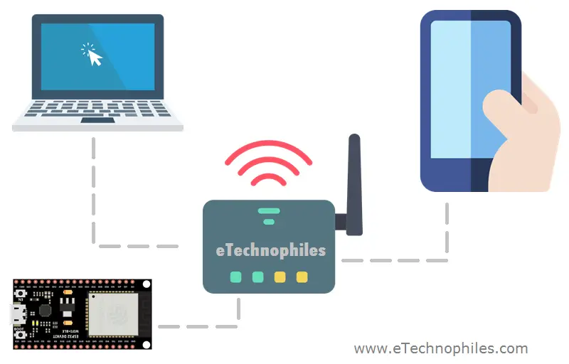
A simple example of this is a website/webpage and web browser. A website is hosted by a server located somewhere. This server is actually a computer providing data space for the website. Whereas the web browser program is a client, which requests data from the website when a user clicks on the website link or types the URL in the browser’s search bar.
Note: The communication between the client and server takes place using Hypertext transfer protocol(HTTP).
What is an ESP32 Web Server?
In this tutorial, you are going to create an HTML Webpage that displays content like buttons and text to control the status of the LEDs. This webpage is hosted on ESP32. That’s why it’s called an ESP32 web server.
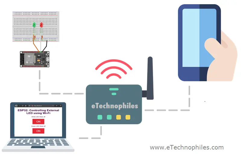
When you enter a unique URL in a web browser, it sends an HTTP request to ESP32 to handle this request. When ESP32 reads this request, it knows that it has to display the content of the webpage(attached to the specific URL). All of this is programmed in Arduino IDE including that HTML page.
How to create your first ESP32 Web Server
Objective: Create an ESP32 web server to control the status of the LEDs connected at GPIO pin 15 and 5 respectively.
To use the wifi connectivity feature of ESP32, there is a built-in library <WiFi.h> in Arduino IDE. This library is installed automatically after installing the esp32 board in our Arduino IDE.
Materials Required:
- ESP32 Module
- Arduino IDE
- Micro USB cable
- Jumper Wire
- 2 x 100-ohm resistors
- 2 x LED
Circuit Diagram for ESP32 Web Server:
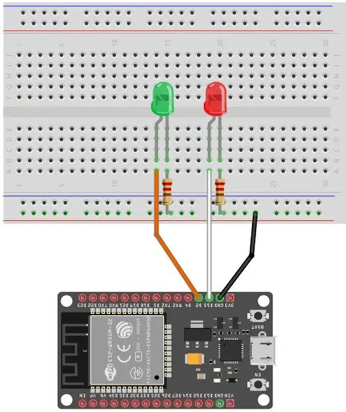
In this project, we are going to use GPIO 15 and GPIO 5 for connecting our LEDs to the ESP32 board as shown in the circuit diagram given below.
Step 1: Connect the ESP32 module to the computer through a micro-USB cable. The RED LED on the board lights up once the board is powered.
Step 2: Go to Tools> Board from the top menu and click on the “ESP32 Arduino” option. Now select the ESP32 board type you are using. I have selected the ESP32 dev module.
Step 3: Now go to Tools>Port, and select the port to which the board is connected.
Step 4: Paste/write the ESP32 web server program given below in Arduino IDE.
ESP32 Web Server Program:
#include <WiFi.h> // Load Wi-Fi library

// Replace with your network credentials
const char ssid[] = "ARYAN";
const char password[] = "********";

// Set web server port number to 80 default HTTP port
WiFiServer server(80);

// Variable to store the HTTP request
String header;

//Variables to store the current output state of LED
String whiteLEDState = "off";
String greenLEDState = "off";

// Assign output variables to GPIO pins
const int whiteLED = 15;
const int greenLED = 5;

void setup() {
  Serial.begin(115200);
  // Initialize the output variables as outputs
  pinMode(whiteLED, OUTPUT);
  pinMode(greenLED, OUTPUT);
  // Set outputs to LOW
  digitalWrite(whiteLED, LOW);
  digitalWrite(greenLED, LOW);

  // Connect to Wi-Fi network with SSID and password
  Serial.print("Connecting to ");
  Serial.println(ssid);
  WiFi.begin(ssid, password);
  while (WiFi.status() != WL_CONNECTED) {
    delay(500);
    Serial.print(".");
  }
  // Print local IP address and start web server
  Serial.println("");
  Serial.println("WiFi connected.");
  Serial.println("IP address: ");
  Serial.println(WiFi.localIP());
  server.begin();
}

void loop(){
  WiFiClient client = server.available();   // Listen for incoming clients

  if (client) {                             // If a new client connects,
    Serial.println("New Client.");          // print a message out in the serial port
    String currentLine = "";                // make a String to hold incoming data from the client
    while (client.connected()) {            // loop while the client's connected
      if (client.available()) {             // if there's bytes to read from the client,
        char c = client.read();             // read a byte, then
        Serial.write(c);                    // print it out the serial monitor
        header += c;
        if (c == '\n') {                    // if the byte is a newline character
          // if the current line is blank, you got two newline characters in a row.
          // that's the end of the client HTTP request, so send a response:
          if (currentLine.length() == 0) {
            // HTTP headers always start with a response code (e.g. HTTP/1.1 200 OK)
            // and a content-type so the client knows what's coming, then a blank line:
            client.println("HTTP/1.1 200 OK");
            client.println("Content-type:text/html");
            client.println("Connection: close");
            client.println();

            // turns the GPIOs on and off
            if (header.indexOf("GET /white/on") >= 0) {
              Serial.println("White LED is on");
              whiteLEDState = "on";
              digitalWrite(whiteLED, HIGH);
            } else if (header.indexOf("GET /white/off") >= 0) {
              Serial.println("White LED is off");
              whiteLEDState = "off";
              digitalWrite(whiteLED, LOW);
            } else if (header.indexOf("GET /green/on") >= 0) {
              Serial.println("Green LED is on");
              greenLEDState = "on";
              digitalWrite(greenLED, HIGH);
            } else if (header.indexOf("GET /green/off") >= 0) {
              Serial.println("Green LED is off");
              greenLEDState = "off";
              digitalWrite(greenLED, LOW);
            }

            // Display the HTML web page
            client.println("<!DOCTYPE html><html>");
            client.println("<head><meta name=\"viewport\" content=\"width=device-width, initial-scale=1\">");
            // CSS to style the on/off buttons
            client.println("<style>html { font-family: Helvetica; display: inline-block; margin: 0px auto; text-align: center;}");
            client.println(".button { background-color: #e62936; border: none; color: white; padding: 16px 40px;");
            client.println("text-decoration: none; font-size: 30px; margin: 2px; cursor: pointer;}");
            client.println(".button2 {background-color: #2a09e6;}</style></head>");

            // Web Page Heading
            client.println("<body><h1>ESP32: Controlling External LED using Wi-Fi</h1>");

            // Display current state, and ON/OFF buttons for GPIO 15
            client.println("<p>White LED State " + whiteLEDState + "</p>");
            // If the whiteLEDState is off, it displays the ON button
            if (whiteLEDState=="off") {
              client.println("<p><a href=\"/white/on\"><button class=\"button\">ON</button></a></p>");
            } else {
              client.println("<p><a href=\"/white/off\"><button class=\"button button2\">OFF</button></a></p>");
            }

            // Display current state, and ON/OFF buttons for GPIO 5
            client.println("<p>Green LED State " + greenLEDState + "</p>");
            // If the greenLEDState is off, it displays the ON button
            if (greenLEDState=="off") {
              client.println("<p><a href=\"/green/on\"><button class=\"button\">ON</button></a></p>");
            } else {
              client.println("<p><a href=\"/green/off\"><button class=\"button button2\">OFF</button></a></p>");
            }
            client.println("</body></html>");

            // The HTTP response ends with another blank line
            client.println();
            // Break out of the while loop
            break;
          } else { // if you got a newline, then clear currentLine
            currentLine = "";
          }
        } else if (c != '\r') {  // if you got anything else but a carriage return character,
          currentLine += c;      // add it to the end of the currentLine
        }
      }
    }
    // Clear the header variable
    header = "";
    // Close the connection
    client.stop();
    Serial.println("Client disconnected.");
    Serial.println("");
  }
}
Step 5: You have to modify the following code with your network OR hotspot(router, smartphone) credentials i.e, the network’s SSID and Password.
const char ssid[] = "Write your network SSID";
const char password[] = "Network Password";
Step 6: Click the upload option to upload the code. Don’t forget to press and hold the BOOT button during the uploading process.
Step 7: Open the serial monitor on the Arduino IDE by going to Tool>Serial Monitor or by pressing Ctrl+Shift+M.
Step 8: Now press the RESET button on the ESP32 board.
Step 9: Upon correct SSID and Password details of the network, the serial monitor shows a successful Wi-fi connectivity message and prints out an IP address.
Step 10: Paste the IP address in your browser to access the ESP32 web server.
Note: The device(mobile or laptop) must be connected to the same network/router to which the ESP32 board is connected.
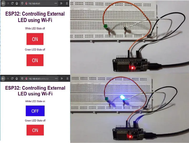
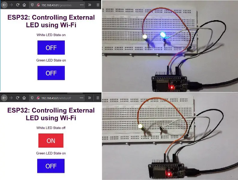
- Upon entering the correct IP, the ESP32 web server displays the HTML page shown below:

- Control the status of the LED by pressing the respective buttons.

Code explanation:
#include <WiFi.h>
- #include is used to include outside libraries in our program. This gives the user access to a large group of standard C libraries (groups of pre-made functions), and also libraries written especially for the ESP32 board.
- Here, we have included the <WiFi.h> library that allows us to use functions that help us to connect the ESP32 board to the internet.
// Replace with your network credentials
const char ssid[] = "ARYAN";
const char password[] = "*********";
- Defining and initializing the character array for storing the Wi-Fi hotspot SSID and password.
// Set web server port number to 80 default HTTP port
WiFiServer server(80);
- Set the webserver port to 80 as it is the default HTTP port for the communication between the server and client.
- NOTE: If you want to use any other port, enter the IP address followed by the port you set- IP Address: PORT
String header;
- Declare a header variable to store the header HTTP request
String whiteLEDState = "off";
String greenLEDState = "off";
- Declare a variable to store the current state of the LED.
const int whiteLED = 15;
const int greenLED = 5;
- Assign the variable to the GPIO pin number.
Inside the void setup() function:
Serial.begin(115200);
- Serial.begin() function starts the serial data communication between the Arduino board and the Arduino IDE.
- The argument of the Serial.begin() function sets the data rate in bits per second (baud) for serial data transmission. Here we are setting the data rate as 115200 bits per second.
- Supported baud rates are 300, 600, 1200, 2400, 4800, 9600, 14400, 19200, 28800, 31250, 38400, 57600, and 115200.
pinMode(whiteLED, OUTPUT);
pinMode(greenLED, OUTPUT);
- Here, we are initializing the mode of the whiteLED and greenLED GPIO pin as OUTPUT.
  digitalWrite(whiteLED, LOW);
  digitalWrite(greenLED, LOW);
- The digitalWrite() function is used to set both the white and green LED to the OFF state.
Serial.print("Connecting to ");
  Serial.println(ssid);
  WiFi.begin(ssid, password);
  while (WiFi.status() != WL_CONNECTED) {
    delay(500);
    Serial.print(".");
  }
- The above code snippet using the provided SSID and password establish the connection between the ESP32 board and Wi-Fi hotspot
  Serial.println("");
  Serial.println("WiFi connected.");
  Serial.println("IP address: ");
  Serial.println(WiFi.localIP());
- This code prints the success message after a successful connection with the hotspot and also prints the IP address that will be used to connect to the server.
Server.begin()
- This function tells the server to begin listening for the external HTTP requests.
Inside the loop() function:
WiFiClient client = server.available();
- This sets the client object as TRUE whenever a client is connected to the server and has data available for reading.
if (client) {                             // If a new client connects,
Serial.println("New Client.");          // print a message out in the serial port
String currentLine = "";                // make a String to hold incoming data from the client
while (client.connected()) {            // loop while the client's connected
if (client.available()) {             // if there's bytes to read from the client,
char c = client.read();             // read a byte, then
Serial.write(c);                    // print it out the serial monitor
header += c;
if (c == '\n') {                    // if the byte is a newline character
// if the current line is blank, you got two newline characters in a row.
// that's the end of the client HTTP request, so send a response:
if (currentLine.length() == 0) {
// HTTP headers always start with a response code (e.g. HTTP/1.1 200 OK)
// and a content-type so the client knows what's coming, then a blank line:
client.println("HTTP/1.1 200 OK");
client.println("Content-type:text/html");
client.println("Connection: close");
client.println();
- Now if the client is connected and is requesting the HTTP communication, the statements above start receiving data from the client and stores the data in the header string.
- And it will continue to receive the data until ‘\n’ is not found which means the client is disconnected.
If statement to check which button is pressed:
if (header.indexOf("GET /white/on") >= 0) {
Serial.println("White LED is on");
whiteLEDState = "on";
digitalWrite(whiteLED, HIGH);
} else if (header.indexOf("GET /white/off") >= 0) {
Serial.println("White LED is off");
whiteLEDState = "off";
digitalWrite(whiteLED, LOW);
} else if (header.indexOf("GET /green/on") >= 0) {
Serial.println("Green LED is on");
greenLEDState = "on";
digitalWrite(greenLED, HIGH);
} else if (header.indexOf("GET /green/off") >= 0) {
Serial.println("Green LED is off");
greenLEDState = "off";
digitalWrite(greenLED, LOW);
}
- The above code snippet checks which button present on the webpage is pressed and according to it a unique request is sent to the server and the appropriate action is taken.
- For example– when the ON button is pressed for the green LED, the “GET /green/on” request is sent(HTTP request for a different URL page)
- Then using the digitalWrite function the LED is set to HIGH and also the state variable of the LED is changed to ON. The displayed text over the Green button also changes to OFF.
Creating the HTML web page:
The graphical user interface that you see after entering the IP in the browser is actually an HTML page. This responsive webpage is created in the Arduino IDE as explained below:
client.println("<!DOCTYPE html><html>");
client.println("<head><meta name=\"viewport\" content=\"width=device-width, initial-scale=1\">");
client.println("<link rel=\"icon\" href=\"data:,\">");
- Client.println() function is used to send the data to our browser.
- The HTML page is created by starting the page with <HTML> tag and followed by the <head> tag that consists of viewport attribute to make the page compatible for all the browsers and devices.
Styling the HTML page using CSS:
client.println("<style>html { font-family: Helvetica; display: inline-block; margin: 0px auto; text-align: center;}");
client.println(".button { background-color: #e62936; border: none; color: white; padding: 16px 40px;");
client.println("text-decoration: none; font-size: 30px; margin: 2px; cursor: pointer;}"); client.println(".button2 {background-color: #2a09e6;}</style></head>");
- The <style> tag is used to make the web page more creative and beautiful by changing the font, font-size, margin, and text alignment.
- We can also create a class inside the <style> tag, here we have created two class buttons and button2. Button class before the button on the web page is not pressed and button2 when the button on the web page is pressed.
<Body> tag of the HTML page:
// Web Page Heading
client.println("<body><h1>ESP32: Controlling External LED using Wi-Fi</h1>");
- This sets the top heading of the webpage to “ESP32: Controlling External LED using Wi-Fi” as shown below:
client.println("<p>White LED State " + whiteLEDState + "</p>");
Display the current state of white LED
// If the whiteLEDState is off, it displays the ON button
if (whiteLEDState=="off") {
client.println("<p><a href=\"/white/on\"><button class=\"button\">ON</button></a></p>");
} else {
client.println("<p><a href=\"/white/off\"><button class=\"button button2\">OFF</button></a></p>");
}
- This code displays the current state of White LED and also creates a button for controlling the white LED in the webpage.
// Display current state, and ON/OFF buttons for GPIO 5
client.println("<p>Green LED State " + greenLEDState + "</p>");
// If the greenLEDState is off, it displays the ON button
if (greenLEDState=="off") { client.println("<p><a href=\"/green/on\"><button class=\"button\">ON</button></a></p>"); }
else {
client.println("<p><a href=\"/green/off\"><button class=\"button button2\">OFF</button></a></p>");
}
- This code displays the current state of green LED and also creates a button for controlling the green LED in the webpage.
client.println("</body></html>");
- Finally we close the <body> tag and <html> tag to create the web page.
header = "";
client.stop();
Serial.println("Client disconnected.");
Serial.println("");
 }
- And at last, we clear the header variable after sending the response from the server and later disconnect the client and print a successful “Client Disconnected” message in the serial monitor.
Demo of ESP32 Web Server Project:
