Last updated on March 26th, 2021 at 08:54 pm
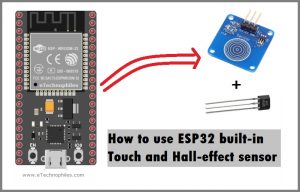
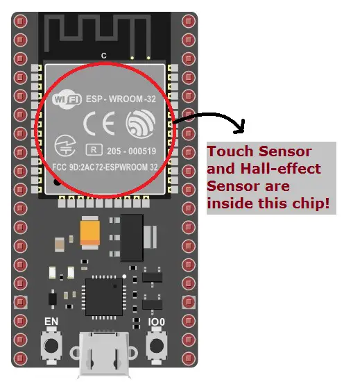
ESP32 Touch and Hall effect sensor are built-in inside the ESP Wroom 32 microcontroller chip. Both the sensors are easy to program and can be used in small projects. So by the end of this article, you would be able to use and program the ESP32 Touch and Hall effect Sensor with Arduino IDE.
| << Previous Tutorial:
ESP32 Blinking Led tutorial using GPIO control with Arduino IDE |
ESP32 Touch Sensor Project:
The ESP32 board comes with 10 capacitive touch sensors connected to GPIO pins as shown in the ESP32 Pinout figure given below:
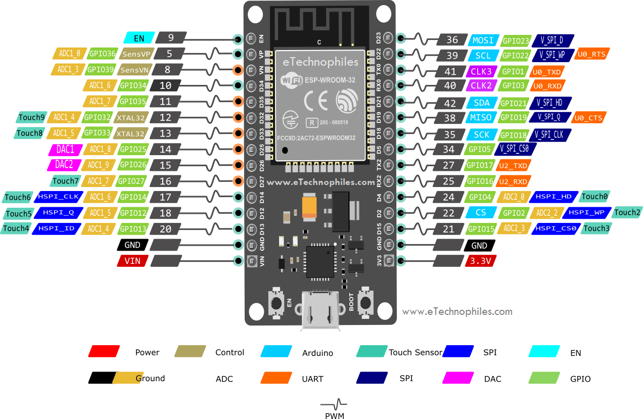
Note: ESP32 boards with 30,36 and 38 pins have the same number of touch sensor pins i.e, 10.
These GPIO pins(having a touch sensor) when touched can sense variations in objects that conduct electricity. Like the human skin. So, when you touch the GPIO pin with your finger, it generates some variations. And these variations are read by the sensor.
To read analog values from the touch sensor, an inbuilt function “touchRead()“ is used. This function accepts the GPIO pin number as the argument.
Syntax–touchRead(GPIO_pin);
Materials Required:
- ESP32 Module
- Arduino IDE
- Micro USB cable
- Jumper Wires
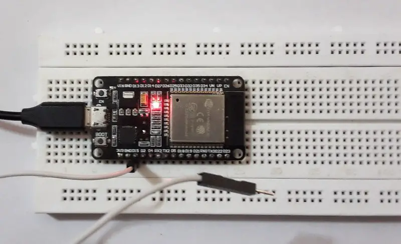
Step 1: Connect the ESP32 module to the computer through a micro-USB cable. The RED LED on the board lights up once the board is powered.
Step 2: Connect one end of the jumper wire to the GPIO Pin 15. And leave the other end as it is(unconnected). I am using GPIO 15 here. You may use any other GPIO pin having a built-in touch sensor.
Step 3: Go to Tools> Board from the top menu and click on the “ESP32 Arduino” option. Now select the ESP32 board type you are using. I have selected the ESP32 dev module.
Step 4: Now go to Tools>Port, and select the port to which the board is connected.
Step 5: Paste/write the ESP32 touch sensor program given below in Arduino IDE.
Step 6: Click the upload option to upload the code. Don’t forget to press and hold the BOOT button during the uploading process.
Program to use ESP32 Touch Sensor:
#define LED_BuiltIn 2
void setup() {
  // put your setup code here, to run once:
  pinMode(LED_BuiltIn,OUTPUT);
  Serial.begin(115200);
  delay(1000); // stop the execution for 1 sec
  Serial.println("ESP32 Touch sensor value");
}

void loop() {
  // put your main code here, to run repeatedly:
  Serial.println(touchRead(15));
  delay(1000);
  if (touchRead(15)<40)
  {
    digitalWrite(LED_BuiltIn,HIGH);
    delay(500);
    digitalWrite(LED_BuiltIn,LOW);
  }
}
OBJECTIVE: When the jumper wire connected to the GPIO pin 15 is touched, the inbuilt LED of the esp32 board lights up.
Code Explanation:
#define LED_BuiltIn 2
- Define the macro for Pin 2 called LED_BUILTIN. Defining macros simplifies your program. Whenever the name LED_BUILTIN appears in the program, the compiler changes it to pin no. 2 automatically.
- So to use a pin other than GPIO pin 2, you just have to change the GPIO PIN at one place only i.e, where you have defined the macro for GPIO pin 2.
Note: Macros are defined outside the functions and at the beginning of the program.
Inside the void setup() function:
Note: The setup() function is called as soon as the program starts executing. It is used to initialize variables and set the mode of the GPIO pins. Setup() function is executed only once.
pinMode(LED_BuiltIn,OUTPUT);
- Here, we are initializing the mode of the LED_BuiltIn GPIO pin as OUTPUT.
Serial.begin(115200);
- Serial.begin() function starts the serial data communication between the Arduino board and the Arduino IDE.
- The argument of the Serial.begin() function sets the data rate in bits per second (baud) for serial data transmission. Here we are setting the data rate as 115200 bits per second.
- Supported baud rates are 300, 600, 1200, 2400, 4800, 9600, 14400, 19200, 28800, 31250, 38400, 57600, and 115200.
delay(1000);
Serial.println("ESP32 Touch sensor value");
- The delay() function is used to stop/pause the execution of the program for 1000 milliseconds (1 second). In order to wait for the serial monitor to start.
- And the Serial.println() function is used to print the data to the serial port in the human-readable ASCII format followed by a return character (“\r”) and a newline character (“\n”).
- Here, I am printing the string “ESP32 Touch sensor value” on the serial monitor of Arduino.
- To open the serial monitor, go to Tools>Serial monitor or press Ctrl+Shift+M. Then select the baud rate 115200 from the drop-down menu present at the bottom right corner of the serial monitor.
Note: Make sure the Arduino board is connected to the PC and right COM port is selected.
Inside the void loop() function:
Note: After the execution of the setup() function, the execution loop() function begins. Its function is to continuously run the code written inside of it in an infinite loop. That’s why it’s called a void loop().
Serial.println(touchRead(15));
delay(1000);
- Serial.println() function prints the value returned by the touchRead() function.
- As explained earlier, the touchRead() function is used to read the value of the touch sensor by accepting the GPIO pin number as the argument. And with the increase in touch-force on the wire, the value returned by the touchRead() increases.
- The delay() function stops the program for 1 second (1000 milliseconds).
if (touchRead(15)<40)
{.....}
- if-else statements are called conditional statements.
- If the condition inside the () bracket is true, the statements inside the if {} block is executed.
- If the condition inside the () bracket is false, the compiler skips the code/statement inside the if {} block.
- In the program given above, when the touchRead() function returns a value greater than 40, statements inside the if{} block is executed.
Statements inside the if() block:
digitalWrite(LED_BuiltIn,HIGH);
delay(500);
digitalWrite(LED_BuiltIn,LOW);
delay(500);
- It’s a simple LED blinking program. First, the digitalWrite() function turns ON the inbuilt LED.
- Then there is a delay of 500 milliseconds.
- The digitalWrite() function turns OFF the inbuilt LED.
- Again there is a delay of 500 milliseconds.
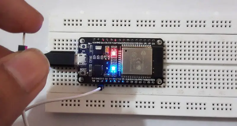
Step 6: Touch the jumper wire connected to the respective GPIO pin and observe the readings on the serial monitor.
So the outcome of this project is: when you touch the jumper wire connected to the GPIO pin 15, the inbuilt LED of the esp32 board lights up.
ESP32 Hall Effect Sensor Project:
The ESP32 board has a built-in Hall Effect sensor also. This sensor is a simple piece of wire with a continuous current flowing through it.
When the magnetic field is placed around it, the charge carriers, electrons, and holes are deflected to either side. This deflection or imbalance generates a voltage difference across the sensor material. This generated voltage difference is used to measure the strength of the magnetic field.
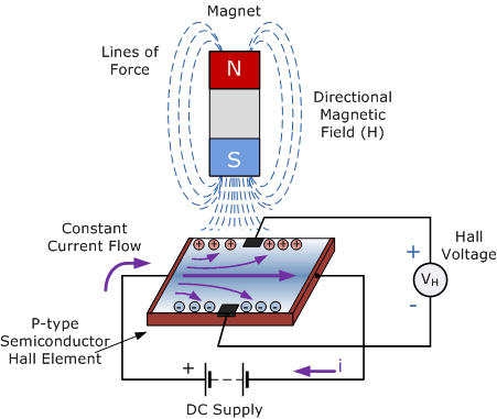
Image Source: Read this excellent article to know more about Hall Effect sensors.
NOTE: The Arduino IDE has a hallRead() function that returns this voltage difference generated by the magnetic field in the form of analog value(stronger the external magnetic field, larger is the analog value returned by the function).
Materials Required:
- ESP32 Module
- Arduino IDE
- Micro USB cable
- Small Magnet
Step 1: Connect the ESP32 module to the computer through a micro-USB cable. The RED LED on the board lights up once the board is powered.
Step 2: Go to Tools> Board from the top menu and click on the “ESP32 Arduino” option. Now select the ESP32 board type you are using. I have selected the ESP32 dev module.
Step 3: Now go to Tools>Port, and select the port to which the board is connected.
Step 4: Paste/write the ESP32 hall effect program given below in Arduino IDE.
Step 5: Click the upload option to upload the code. Don’t forget to press and hold the BOOT button during the uploading process.
Program to use ESP32 Hall-effect Sensor:
int magnetic_value=0;
void setup() {
  // put your setup code here, to run once:
  Serial.begin(115200);
}

void loop() {
  // put your main code here, to run repeatedly:
  magnetic_value=hallRead();
  Serial.print("ESP32 Hall effect sensor value value: ");
  Serial.println(magnetic_value);
  delay(2000);
}
OBJECTIVE: Print the values returned by the built-in hall effect sensor.
Code Explanation:
int magnetic_value=0;
- Declare a variable named magnetic_value of the integer data type to hold the value returned by the hallRead() function.
Inside the void setup() function:
Serial.begin(115200);
- Serial.begin() function starts the serial data communication between the Arduino board and the Arduino IDE.
- The argument of the Serial.begin() function sets the data rate in bits per second (baud) for serial data transmission. Here we are setting the data rate as 115200 bits per second.
- Supported baud rates are 300, 600, 1200, 2400, 4800, 9600, 14400, 19200, 28800, 31250, 38400, 57600, and 115200.
Inside the void loop() function:
magnetic_value=hallRead();
- Assign the value return by the hallRead() function to the variable declared above i.e., magnetic_value.
Serial.print("ESP32 Hall effect sensor value value: ");
Serial.println(magnetic_value);
delay(2000);
- Serial.println() function prints the value returned by the hallRead() function by using the variable magnetic_value.
- As explained earlier, the hallRead() function is used to read the value of the hall effect sensor by accepting the GPIO pin number as the argument. And with the increase in the external magnetic field around the sensor, the value returned by the hallRead() increases.
- The delay() function stops the program for 1 second (1000 milliseconds).
NOTE: And as these statements are inside the loop() function, the code runs in an infinite loop and prints the sensor values every second.
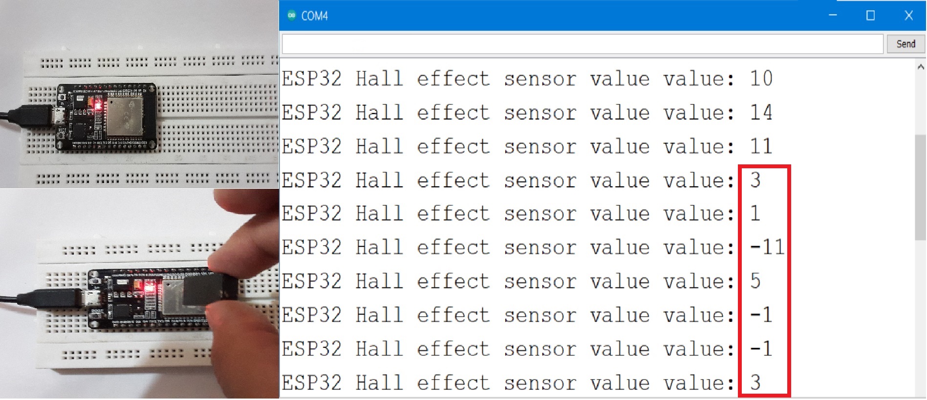
Step 6: Place the magnet directly above the ESP32 Wroom chip and observe the readings on the serial monitor. Bring the magnet closer to the chip or rotate the face of the magnet 180 degrees.
Note: Negative reading means the electrons are deflected to the other side now OR the magnet facing the chip is turned 180 degrees.
