Last updated on May 24th, 2021 at 01:34 pm
In the previous tutorial on ESP32, we went through the process of setting up the ESP32 library on Arduino IDE. In this article, we are going to use the Arduino IDE to control the inbuilt programmable LED of the ESP32 board. After the ESP32 Blinking LED project, we will control some external LEDs connected to the board to understand the basic working of the GPIO pins.
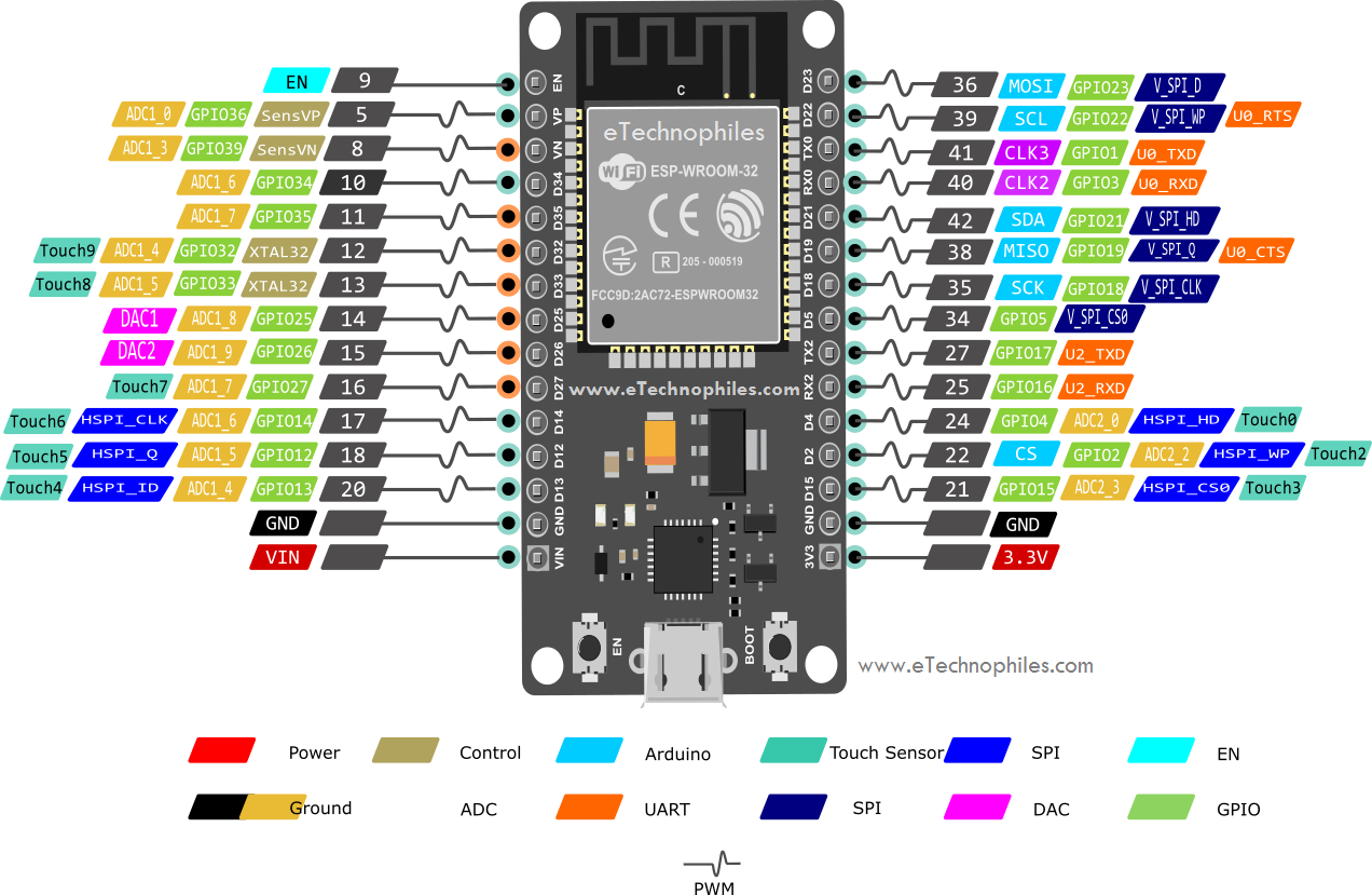
Programming an ESP32 using Arduino IDE is exactly similar to programming any Arduino board. But before programming the inbuilt LED on ESP32 using the Arduino IDE, let’s look at the pinout diagram of the ESP32 board:

esp32 Board Pinout with 30 pins
The inbuilt LED that we want to control is internally connected to the GPIO pin 2(with an inbuilt resistor). This inbuilt LED is BLUE in color.
| >> Previous Tutorial: |
ESP32 Blinking LED project with Arduino IDE:
Materials Required:
- ESP32 Module
- Arduino IDE
- Micro USB cable
Step 1: Connect the ESP32 module to the computer through a micro-USB cable. The RED LED on the board lights up once the board is powered.
Step 2: Go to Tools> Board from the top menu and click on the “ESP32 Arduino” option. Now select the ESP32 board type you are using. I have selected the ESP32 dev module.
Step 3: Now go to Tools>Port, and select the port to which the board is connected.
Step 4: Paste/write the ESP32 Blinking LED program given below in Arduino IDE.
Step 5: Click the upload option to upload the code. Don’t forget to press and hold the BOOT button during the uploading process.
Program to Blink the ESP32’s inbuilt LED:
#define LED_BUILTIN 2 // define the GPIO 2 as LED_BUILTIN
void setup() {
  pinMode(LED_BUILTIN, OUTPUT); // initialize GPIO pin 2 LED_BUILTIN as an output.
}
void loop() {
  digitalWrite(LED_BUILTIN, HIGH);   // turn the LED on
  delay(1000);                       // wait for a second
  digitalWrite(LED_BUILTIN, LOW);    // turn the LED off
  delay(1000);                       // wait for a second
}
Code explanation:
#define LED_BUILTIN 2
Define the macro for Pin 2 called LED_BUILTIN. Defining macros simplifies your program. Whenever the name LED_BUILTIN appears in the program, the compiler changes it to pin no. 2 automatically. So to use a pin other than GPIO pin 2, you just have to change the GPIO pin number at one place only i.e, where you defined the macro for GPIO pin 2.
Note: Macros are defined outside the functions and at the beginning of the program.
Inside the void setup() function:
Note: The setup() function is called whenever the program starts executing. It is used to initialize variables and set the mode of the GPIO pins. Setup() function is executed only once.
pinMode(LED_BUILTIN, OUTPUT);
Here, we are initializing the mode of the LED_BUILTIN GPIO pin as OUTPUT.
Inside the void loop() function:
Note: After the execution of the setup() function, the execution loop() function begins. Its function is to continuously run the code written inside of it in an infinite loop. That’s why it’s called a void loop().
digitalWrite(LED_BUILTIN, HIGH);
delay(1000);
Inside the loop() function, the digitalWrite() function is used to set the GPIO pin to HIGH. This sets the GPIO pin 2 to 5 Volts and the inbuild LED connected to it turns ON. Then a delay() function is used to stop the execution of the program for 1000 milliseconds (1 second).
digitalWrite(LED_BUILTIN, LOW);
delay(1000);
After the delay() function, the digitalWrite() function is used to set the GPIO pin to LOW. This sets the GPIO pin 2 to 0 Volts and the inbuild LED connected to it turns OFF. Another delay() function is used after that to stop the execution of the program for 1 second.
OBJECTIVE: The outcome of this program is that LED remains ON for 1 Second and then turns OFF for another 1 Second.
And as these statements are inside the loop() function, the code keeps repeating and produces the blinking effect of LED.

Now let’s connect some external led to the ESP32 board and write a program to make them blink.
External LEDs control using ESP32 with Arduino IDE:
Material Required:
- ESP32 Module
- Breadboard
- Arduino IDE
- Micro-USB cable
- 2 x 100-ohm resistors
- Some LEDs
Circuit Diagram:

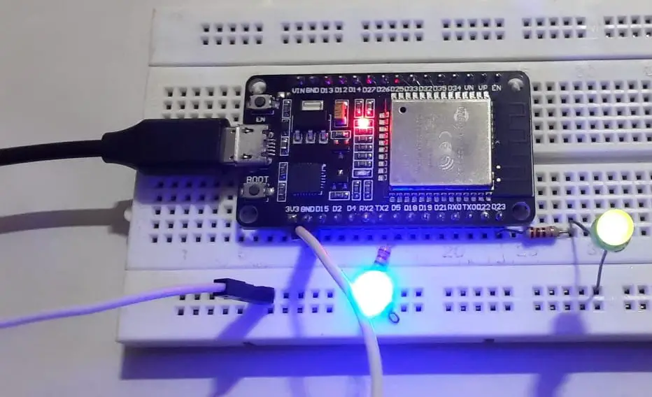
We are going to control the two LEDs using GPIO pins 5 and 23 respectively. Connect the long side of each LED (Anode) to one end of the 100-ohm resistor and the short side (cathode) to the GND pin of the ESP32 board. The other end of the resistors goes to the respective GPIO pins as shown in the above diagram.
Step 1: Connect the ESP32 module to your PC through a micro-USB cable. The RED LED on the board lights up once the board is powered.
Step 2: Go to Tools> Board from the top menu and click on the “ESP32 Arduino” option. Now select the ESP32 board type you are using. I have selected the ESP32 dev module.
Step 3: Now go to Tools>Port, and select the port to which the board is connected.
Step 4: Paste/write the ESP32 Blinking LEDs program given below in Arduino IDE.
Step 5: Click the upload option to upload the code. Don’t forget to press and hold the BOOT button during the uploading process.
Program to Blink the external LEDs:
#define LED_blue 5;  // declare the GPIO 5 as LED_blue
#define LED_green=23;  // declare the GPIO 23 as LED_green

void setup() { // initialize the GPIO as OUTPUT
pinMode (LED_blue, OUTPUT);
pinMode (LED_green, OUTPUT);
}

void loop() {
digitalWrite(LED_blue, HIGH);    //turn blue LED ON
digitalWrite(LED_green, HIGH);    //turn green LED ON
delay(2000);                      //wait for 2 sec
digitalWrite(LED_blue, LOW);    //turn blue LED OFF
digitalWrite(LED_green, LOW);   //turn green LED OFF
delay(2000);
}
Code Explanation:
#define LED_blue 5;
#define LED_green=23;
Define the macros LED_blue and LED_green for GPIO pin 5 and 23 respectively. Defining macros simplifies your program. Wherever the names LED_blue and LED_green appear in the program, the compiler assigns the integer 5 and 23 respectively. So to use a pin other than GPIO pin 5 or 23, you just have to change the GPIO pin number at one place only i.e, where you defined the macro for GPIO pin 5.
Note: Macros are defined outside the functions and at the beginning of the program.
Inside the void setup() function:
Note: The setup() function is called whenever the program starts executing. It is used to initialize variables and set the mode of the GPIO pins. Setup() function is executed only once.
pinMode (LED_blue, OUTPUT);
pinMode (LED_green, OUTPUT);
Here, we are initializing the mode of the LED_blue and LED_green GPIO pins as OUTPUT.
Inside the void loop() function:
Note: After the execution of the setup() function, the execution loop() function begins. Its function is to continuously run the code written inside of it in an infinite loop. That’s why it’s called a void loop().
digitalWrite(LED_blue, HIGH); //turn blue LED ON
digitalWrite(LED_green, HIGH); //turn green LED ON
delay(2000);
Inside the loop() function, the digitalWrite() function is used to set the GPIO pins to HIGH. This sets the GPIO pin 5 and 23 to 5 Volts and the LED connected to the pins turns ON. Hence, both the LEDs are turned one at this point. Then a delay() function is used to stop the execution of the program for 2000 milliseconds (2 seconds).
digitalWrite(LED_blue, LOW); //turn blue LED OFF
digitalWrite(LED_green, LOW); //turn green LED OFF
delay(2000);
After the delay() function, the digitalWrite() function is used again. But this time to set the GPIO pins to LOW. This sets the GPIO pin 5 and 23 to 0 Volts and the LED connected to the pins turns OFF. Another delay() function is used after that to stop the execution of the program for 2 seconds.
OBJECTIVE: The outcome of this program is that both LEDs remain ON for 2 seconds and then turn OFF for another 2 seconds.
And as these statements are inside the loop() function, the code keeps repeating and produces the ESP32 blinking LED effect on both the LEDs.

| >> Next Tutorial: |

Hi, the resistors in the circuit diagram dont look like 100 ohm resistors? Shouldnt they be brown-black-brown-gold?
Just checking before I try this. Thankyou
Hi Simon,
That was a mistake from our end.
Yes you have to use 100 ohm resistor.
What version of Arduino software is good and board manager number should I use which is good