Welcome to our guide on ‘How To Test a Relay With a Multimeter.’ Relays are crucial components in electronics and automotive systems, and knowing how to test them can save you time and money. In this article, we’ll walk you through the step-by-step process of testing a relay. Let’s get started.
How do you test a relay with a multimeter?
Check the resistance of the coil and continuity between the terminals of the switching side using the multimeter. Resistance of the coil should fall between 50 and 100. The multimeter beeps when connected to COM and NC terminals. It should produce no sound when probes are touching COM and NO terminals.
| SN. | Test | Expected Value |
|---|---|---|
| 1 | Check resistance bw the ends of the coil | 50Ω~200Ω |
| 2 | Check continuity bw NC-COM | Beep sound |
| 3 | Coil energize- Check continuity bw NO-COM | Beep sound |
Table of Contents
How does a relay work?
Relay is a type of switch activated using a low voltage/current source. So it has two parts: Control or primary and Switch or secondary part. The most common type of relay is an electromagnetic relay.
The control part in an electromagnetic relay is an inductor coil, which creates a magnetic field when an electrical current is applied across it. The switching part is a movable contact that is pulled/pushed when the coil is energized.

The moving contact is also the Common(COM) terminal and touches the Normally closed(NC) terminal. As soon as the coil is energized, it attracts the moving contact toward the Normally open(NO) terminal. This contact moves back to its original state when the coil is de-energized.
Step-by-step guide on testing a relay
1. Identify the relay terminals
Before testing the relay, you should have a clear idea about the terminals of the relay. The first step is identifying the primary side or the coil terminals.
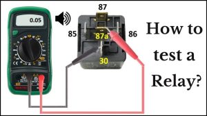
For an automotive relay, the coil terminals are 85 and 86.

The next step is identifying the terminals of the secondary side: NO, NC, and COM terminal. In an automotive relay, these can be easily identified as they have a designated number. 87 for NO, 87a for NC, and 30 for COM. See the table below for easy identification:
In a PCB relay, there are no such markings. So you should check the datasheet of the relay before proceeding. Still, most of the relays follow the pinout shown below:

2. Prepare your multimeter
A multimeter usually has three sockets/ports: COM(common or ground), mAVΩ(voltage or resistance), and 10A(current). Switch on the multimeter and insert the red probe into the mAVΩ socket and the black probe into the COM port.
In order to properly test a relay, you have to check both the primary or coil side and the secondary or switching side. Since the energizing coil is just an inductor, we are going to measure its resistance first.
3. Measure the resistance- Coil side

Select the resistance settings with the Ω symbol and the ‘200Ω’ resistance range using the rotary dial on your multimeter. The ideal resistance of a relay coil is between 50Ω and 200Ω, hence this range. If you have an auto-ranging multimeter, skip this part.

To measure the resistance of the coil, touch its end terminals(85,86) with either of the probes. Touch 85 with the red probe and 86 with the black probe. Now, observe the multimeter reading.
If the resistance value is between 50Ω and 200Ω, then the coil or primary side of the relay is in good condition. If the multimeter displays ‘O.L’, this means there is a break in the coil and the relay is not in usable condition.

4. Continuity test of the switching side before energizing the relay
After confirming the state of the coil, you have to test the switching side of the relay as well. The switching side has three terminals(NO/87, NC/87a & COM/30) as explained in the beginning.
As long as the relay is not energized, the COM terminal is connected to the NC terminal or the moving plate is between COM and NC. We need to test the state of this connection using the continuity function. Select the continuity function with a sound symbol on your multimeter.

Then, touch the NC and COM terminals with the red and black probes, respectively. If the multimeter produces sound, there is continuity between the COM and NC terminals. If the multimeter does not beep or displays high resistance, the relay is defective.
Repeat the same process with COM and NO terminals. Multimeter should not beep as there is an open circuit between these two terminals.
5. Energize the relay and measure continuity- switching side
As we know, when the coil or relay is energized, the moving contact is pulled from the NC terminal to the NO terminal. In this case, there should be no break between the NO and COM terminal and an open circuit between NC and COM. We are going to test this next.
Connect the coil terminals of the relay to a 12V battery or 5V battery(depending on the rating). You will hear a click sound, which means the contact is thrown from NC to NO terminal. Now measure the continuity between NO – COM and NC – COM, respectively.

Touch the NO and COM terminals with the red and black probes, respectively. If the multimeter produces sound, there is continuity between the COM and NO terminals. If the multimeter does not beep or displays high resistance, the relay is defective.
Repeat the same process with COM and NC terminals. Multimeter should not beep as there is an open circuit between these two terminals in this state.
All your eTutorials are great!.
Thank you for sharing and innovating ideas.