Last updated on March 16th, 2024 at 12:37 pm
This article will show you the wiring diagrams of different relays. You will learn how to connect 4-pin (SPST), 5-pin (SPDT), and 8-pin (DPDT) relays to a circuit.
In general, there are only two types of relay you will ever use: breadboard/PCB-friendly relay(for simple electronics projects) and automotive relay(used in automobiles).

Now based on the number of pins, a relay may have 4, 5, 6, and 8 pins. Below is the table explaining each one of them.
| No. of pins | Relay Name | Full form | Function |
|---|---|---|---|
| 4 | SPST | Single pole and Single throw | Single switch, Single config. |
| 5 | SPDT | Single pole and Double throw | Single switch, Two config. |
| 6 | DPST | Double pole and Single throw | Two switches, Two config. |
| 8 | DPDT | Double pole and Double throw | Two switches, Four config. |
Table of Contents
Relay Terminals
Every relay type has these four pins; Coil pins, NO, and COM: 4 and 6-pin relays.

Relays with double throws (two positions) have one extra pin called NC: 5 and 8 pin relay.

Note: Having an NC terminal means there’s a possibility for one more configuration or circuit when the coil is not energized.
In automotive relays, these pins are designated by numbers for easy identification. See the table given below:

| Pin No. | Terminal | Description |
|---|---|---|
| 85 | Coil end | One end of the coil |
| 86 | Coil end | Other end of the coil |
| 87 | NO | Normally Open |
| 87a | NC | Normally Closed(5, 8 pin) |
| 30 | COM | Common terminal |

- Coil terminals: These are the end terminals of the coil inside the relay. When current flows through the coil, created magnetic field pulls the switch contacts together or apart. Either one is connected to the +ve of the power supply. The second terminal is then connected to the -ve of the power supply.
- VCC
- Ground
- Contact terminals: These terminals connect the relay’s contacts to the circuit that needs to be controlled. The contact terminals are typically labeled “NC” (normally closed) and “NO” (normally open), depending on the type of contact.
- Normally open (NO) terminal: This terminal is not connected to the common terminal when the relay is not energized(hence the name ‘normally open’). When the relay is activated, the switch contacts move, and this terminal is connected to the common terminal.
- Normally closed (NC) terminal: This terminal is initially connected to the common terminal when the relay is not energized(hence the name ‘normally open’). When the relay is activated, the switch contacts move, and this terminal is disconnected from the common terminal.
- Common terminal: This terminal is connected to either the NO or NC terminal, depending on the state of the relay, as explained above.
4 Pin Relay Wiring Diagram
A commonly used 4 Pin relay configuration for an Automotive relay is shown by a make-or-break circuit:
Make-or-Break circuit:
This type of circuit can be found in bikes and cars. Initially, when the light switch is off, the circuit is in “Break state.” Hence the headlight remains off. The light switch, when turned on, activates the relay. The circuit moves to “Make state,” causing the headlight to turn on. Now based on the switch position in the circuit, there are two configurations:
Configuration 1: when the Switch is connected to the positive terminal.

- Step 1: Connect one end of the switch to the positive power source (battery).
- Step 2: Connect the other end of the switch to the coil terminal (pin 85 or pin 86) of the relay. In the figure above, the other end of the switch is connected to pin 86.
- Step 3: Connect the ground to the remaining end (pin 86 or pin 85) of the relay. In the above circuit, pin 85 is connected to the ground.
- Step 4: Connect the load (e.g., LED, motor, etc.) to the normally open (NO) terminal (pin 30) of the relay.
- Step 5: Connect the positive power source (battery) to the normally closed (NC) terminal (pin 87) of the relay.
Configuration 2: When the switch is connected to the negative terminal.

- Step 1: Connect one end of the switch to the negative power source (ground).
- Step 2: Connect the other end of the switch to the coil terminal (pin 85 or pin 86) of the relay. In the above circuit, it is connected to pin 85.
- Step 3: Connect the positive power source to the remaining end (pin 86 or pin 85) of the relay. In the above circuit, it is connected to pin 86.
- Step 4: Connect the load (e.g., LED, motor, etc.) to the normally open (NO) terminal (pin 30) of the relay.
- Step 5: Connect the negative power source (ground) to the normally closed (NC) terminal (pin 87) of the relay.
Note: The same circuit can be used to wire a breadboard relay. Just refer to the terminal table given above and follow the same steps.
5 Pin Relay Wiring Diagram
A 5-pin relay can control two devices based on the switch position. When the light switch is off, the second device is on by default(NC position). When the relay is activated(the light switch is on), the second device turns off, and the first device turns on. See the wiring diagram of a 5-pin relay below in both conditions:

- Step 1: Connect one end of the switch to the positive power source.
- Step 2: Connect the other end of the switch to the coil terminal (pin 85 or pin 86) of the relay. Here it is connected to pin 85.
- Step 3: Connect the ground to the remaining end (pin 86 or pin 85) of the relay. Here it is connected to pin 86.
- Step 4: Connect the first load (e.g., LED, motor, etc.) to the normally open (NO) terminal (pin 30) of the relay.
- Step 5: Connect the second load to the changeover (C/O) terminal (pin 87).
- Step 6: Connect the positive power source to the normally closed (NC) terminal (pin 87a) of the relay.
SPDT relay circuit diagram
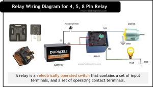
Given below is the wiring diagram of a 5-pin PCB relay. The bulb is on and the motor is off in the initial state. After pressing the pushbutton: motor turns on and the bulb switches off.

8 Pin relay circuit diagram
An 8-pin relay is a DPDT relay (aka double throw relays). Since it has two poles and two throws, it’s possible to control four devices using it. Given below is the wiring diagram of an 8-pin relay:

Case1: When the relay is not activated
In this case, COM terminals are connected to the NC terminals. Hence bulb1, bulb2 and motor1, motor2 are ON and OFF, respectively.
Case2: When the relay is activated
In this case, COM terminals are connected to the NO terminals. Hence bulb1, bulb2 and motor1, motor2 are OFF and ON, respectively.