Last updated on April 2nd, 2024 at 11:15 am
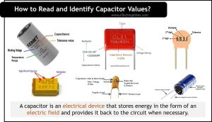
A capacitor is an electrical device that stores energy in the form of an electric field and provides it back to the circuit when necessary. Before using them in the circuit, we need to identify the capacitors as per our circuit requirements.
In this article, we will explain how to read capacitor values that are available in the market. Although some capacitor types may not follow these methods, so do not get confused.
Table of Contents
Before identifying any capacitor’s value, we need to know about the following parameters:
- Capacitance value and its unit
- Tolerance level
- Max working voltage
- Polarity
Electrolytic capacitor
An electrolytic capacitor is a type that uses an electrolyte to achieve a higher capacitance than other capacitor types. There are of three different types (based on their construction material and size): Aluminum, Tantalum, and Niobium electrolytic capacitors.
Capacitance

The capacitance value is written on its outer cover. The unit of capacitance is also mentioned with the capacitor value. Electrolytic capacitors are available in the range of 0.1 μF to 4700 μF.
The base unit of capacitance is the farad (F). But this value is too large for circuits, therefore Aluminum electrolytic capacitors are mostly labeled with microfarad unit (µF). (1 µF, = 1 microfarad = 10-6 farads)
Tolerance value
The tolerance value is also printed on the capacitor. Electrolytic capacitors have a large tolerance (approx. 10 to 20%). This means that an electrolytic capacitor with a nominal capacitance of 100uF is expected to have a measured value of anywhere between 80uF and 120uF.
Voltage rating

The third parameter of a capacitor is its voltage rating. For aluminum electrolytic capacitors this value is also printed on the enclosure (after the capacitance value). The working voltage range can be from 10 V to 450 V.
Note: Since it is a type of DC capacitor so never connect it to an AC voltage source, otherwise, it may damage the capacitor.
Polarity

After reading the above three parameters, we need to know one important parameter which is the capacitor’s polarity. Since an electrolytic capacitor is polarised in nature, we can identify its polarity in the following ways:
- By checking the polarity signs (+ or -) next to any one of the terminals. Connect ‘+’ with the positive terminal and ‘-’ with the negative one of the circuit.
- Besides this, we can also see the positive lead of the capacitor is longer than its negative lead, so you can identify their polarity based on lead size.
- Sometimes these capacitors (shaped like tin cans) use a colored bar or a ring-shaped depression to show polarity, this mark designates the negative end and must be connected with the negative terminal of the circuit.
Note: If capacitors are connected incorrectly they can be damaged, and in some cases, they might also explode.
Tantalum capacitor
Tantalum capacitors are a subtype of electrolytic capacitors. They are smaller in size than aluminum electrolytic capacitors and use tantalum metal which results in a high capacitance value per volume. Tantalum capacitors are DC capacitors similar to electrolytic capacitors.
Capacitance value

Their size is relatively smaller than aluminum capacitors, so, it is difficult to print their capacitance directly, that’s why manufacturers mention only the codes for it. They have capacitance values ranging between nanofarads (nF) to milifarads (mF).
On radial tantalum capacitors, the first two digits of the code shows the capacitance value in microfarads(uF). To denote the capacitance unit, sometimes the ‘u’ letter is printed after two digits.
Tolerance value
Since tantalum capacitors are smaller it has two different tolerance values. (For ±10%, the letter code “K” is used and for ±20%, the letter code “M” is used).
Voltage Rating
For the radial tantalum capacitors after the capacitance code, another two-digit code shows the maximum voltage rating of the capacitor. The unit of working voltage is always in volts(V).
In the case of SMD tantalum capacitors, working voltage is marked in alphabetical codes; i.e. E, G, J, A… etc. We have provided the table of capacitor voltage table in the SMD section below.
Polarity
Tantalum capacitors are polarized capacitors. Usually, their positive terminal is marked on the casing.
Ceramic capacitor
Ceramic capacitors are non-polarized capacitors and are very small in size. It uses a ceramic material as the dielectric. Most ceramic capacitors often used are the multi-layer ceramic capacitor, (named ceramic multi-layer chip capacitor (MLCC) and the ceramic disc capacitor.
Capacitance value

Ceramic capacitors are very small, so their capacitance is always represented in a three-digit number. The unit is mentioned in pF(picofarad). It has a wide range of capacitance values ranging from 10pF(picofarad) to 100μF(microfarad).
In the above figure, out of the three digits, the first two represent the significant value of capacitance and the third one is its multiplier. In this case, 68 is the digit and 3 is the multiplier. So, 68 multiplied by 10^3 (= 68000). Hence the value of this capacitor will be 68000 pF.
Tolerance
The tolerance value is mentioned as a letter code just after its capacitance value. It can vary between 1- 20% depending upon the types (Class I and Class II). With the help of the given table, you can check the tolerance percentage level of any ceramic capacitor.

Working voltage
The operating voltage range for a ceramic capacitor is 16 volts to 15 kV. There are different types of representations for the voltage rating of these capacitors.
- Sometimes it is written clearly on the enclosure of the capacitor with its unit.
- For some disk capacitors, it is represented by a single underline after the capacitance value. This underline shows 100 V as the maximum working voltage.
- If there is nothing mentioned about the voltage on the ceramic capacitor then it is rated at 50V.
Polarity
Ceramic capacitors are non-polarized capacitors so they can be connected to any terminal in the circuit.
Since these are non-polarized, we can use them in either AC or DC circuits.
Film capacitor
Film capacitors are capacitors that use a thin plastic film as the dielectric. There are many types of film capacitors, including polyester film, metalized film, polypropylene film, PTFE film, and polystyrene film. The basic difference between these types is the material used as the dielectric in the capacitor.
Capacitance value

They are medium in size so the capacitance value is mentioned on their cover properly with its measurement unit (i.e. uF or pF). The capacitance range for any film capacitor varies between 100 pF(picofarad) to 22 μF(microfarad).
Sometimes capacitance is specified in the form of a three-digit code. For that, we need to calculate the capacitance value similar to the SMD tantalum capacitor.
Tolerance
Film capacitors are the most precise capacitors in terms of their capacitance value, which means they have a very less tolerance value (Range – 0.1% to 5%) as compared to other types of capacitors.
In most of the plastic and metalized film capacitors, the tolerance value is written just after the capacitance value. If it is not specified then the tolerance level is approx. 5%.
Working voltage
They operate in a voltage range as low as 16V and up to above 2kV. The maximum working voltage rating of these capacitors is printed on the cover of the capacitor.
Note: A film capacitor either works on AC or DC. So we have to check the voltage type before using it. (i.e., VDC for DC voltage and VAC for AC voltage)
Polarity
These are not polarized, so we can connect any one of the terminals interchangeably in the circuit.
SMD capacitor
SMD (Surface Mount Device) is a technology to create very small-size capacitors that can be mounted on PCB in large density.
Capacitance value

It uses a three-digit code style to display the capacitance. The first two figures refer to the significant figures of the capacitor value, and the third one acts as a multiplier. The value of the capacitor is denoted in picofarads.
For example, in the above figure, three digits are 475; 47 is a significant value while 5 is multiplier means (10^5= 100000). So here value of capacitance 4700000 pF (picofarad) is equal to 4.7 uF (microfarad).
| THIRD FIGURE | MULTIPLIER |
|---|---|
| 0 | 1 |
| 1 | 10 |
| 2 | 100 |
| 3 | 1000 |
| 4 | 10 000 |
| 5 | 100 000 |
| 6 | 1 000 000 |
Tolerance
The tolerance value of SMD capacitors depends on whether it is an electrolytic, tantalum, or ceramic capacitor. But in most cases it’s max. tolerance value varies up to 20%. In some capacitors, their capacitance value is mentioned on their top.
Working voltage
Due to their tiny size, the voltage of the SMD capacitors is represented as a letter just after its capacitance value on the outer envelope.
In the below-given table, you can check or match the voltage of SMD electrolyte and tantalum capacitors
Note: Ceramic SMD capacitors are even smaller than others so, they are more difficult to identify. So manufacturers provide an ordering table with it, where they mention their standard coded names. With this, every parameter can be found easily.
Polarity
SMD capacitors can either be polarized or non-polarized capacitors. (For ex: electrolytic and tantalum both are polarized but ceramics are non-polarized).
- In the case of electrolytic or tantalum SMD capacitors, their polarity is marked by a white or black line at one of the device’s ends. This line/bar indicates the positive terminal of the capacitor and the other side is the negative terminal.
- In the case of ceramic or non-polarized capacitors, there is no such indication as a bar or colored dash. These nonpolar ceramic capacitors are generally brown, yellowish-brown, or grey.
So, we hope that after reading this article you might have got the idea, of how to read and identify capacitor values. If there are any doubts, you can tell us in the comments below.
FAQs
How do you decode the value of a capacitor?
If a capacitor is marked “104,” the first two digits “10” represent the capacitance value’s first two significant digits. The third digit “4” indicates the multiplier. Therefore, the capacitance value10 * 10^4 pF, or 100,000 pF (100 nF).
What is 103 capacitor value?
A capacitor marked as “103” indicates a capacitance value of 10 * 10^3 picofarads (pF). This is equivalent to 10,000 pF or 10 nanofarads (nF).
What does 473k mean on a capacitor?
The marking “473k” on a capacitor indicates a capacitance value of 47 * 10^3 pF, which equals 47,000 pF or 47 nanofarads (nF). The “k” represents a tolerance code, often indicating a tolerance of ±10%.