Last updated on September 13th, 2023 at 12:05 pm
A relay is a device that controls a switch position(ON or OFF) connected to a high-current circuit using a low-current signal. So it has two parts: Control and Switch part.
Think of a relay like a gatekeeper or a traffic signal. When a car or pedestrian wants to cross a street, they have to wait for the signal to turn green or for the gatekeeper to open the gate. Similarly, in an electrical circuit, a relay acts as a gatekeeper, controlling the flow of electricity based on the signals it receives.
There are many ways to control the switch position, using an electromagnet, optocoupler, etc. The most famous method is by using an electromagnet. This type of relay is called an electromagnetic relay and is often referred to as Relay. It consists of a coil, which creates a magnetic field when an electrical current is applied, and a set of contacts that open or close in response to that magnetic field.
Relays are employed in a variety of tasks, such as operating electric motors, turning on and off lights and other appliances, and establishing isolation between circuits. They are frequently utilized in industrial and automotive applications, control systems, and automation.
Looking for Relay wiring diagrams? Read this article: Relay Wiring Diagram for 4, 5, 8 Pin & Automotive Relay
Relay Symbol & Terminology
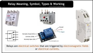
A relay is normally denoted by the symbol shown below.

A relay typically has several terminals that are used to connect the relay to other components in a circuit. Given below is the SPDT relay:

- Coil terminals: These terminals are used to connect the coil of the relay to the power source. The coil terminals are typically labeled “COM” (common) and “NC” (normally closed) or “NO” (normally open).
- Contact terminals: These terminals are used to connect the relay’s contacts to the rest of the circuit. The contact terminals are typically labeled “NC” (normally closed) and “NO” (normally open), depending on the type of contact.
- Common terminal: This terminal is the common point of the relay and the point where the current flows through the relay. It is typically labeled “COM” (common)
- Normally open terminal: This terminal is the one that remains open unless the coil is energized, it is typically labeled “NO”
- Normally closed terminal: This terminal is the one that remains closed unless the coil is energized, it is typically labeled “NC”
- Additional terminals like DC or AC coil terminals, and auxiliary contact terminals are present in some relays.
Note: It’s important to note that the specific terminals and their labeling may vary depending on the manufacturer and the type of relay. It’s always best to consult the datasheet of the relay for the terminal information.
Working of Relay
Electric current and electromagnetic field are two fundamental components required to operate a relay.
Before understanding this in detail, let’s look at some of the terms used in relay operations.
- Pick-up current: The amount of current needed to energize a relay’s coil is called the pick-up current.
- Pick-up voltage: The minimum voltage at which a relay will switch on is called the pick-up voltage.
- Drop-out current: The amount of current at which a relay will de-energize is called the drop-out current.
- Drop-out voltage: The maximum voltage at which a relay will switch off is called the drop-out voltage.

Consider a 5V relay whose primary coils are connected to a 5V DC source through a switch. On the secondary side, the armature remains at the Normally closed (NC) position. The load is connected to the Normally closed (NO) position. So, in this case, the secondary circuit is open, and no current flows.
When the primary coil gets energized, the electromagnet attracts the armature and its position gets shifted to Normally open (NO). In this case, the secondary circuit gets completed and the current starts flowing.
So, the basic principle of all the relays is the same. By energizing and de-energizing an electromagnet the position of the armature is changed, and a secondary circuit is controlled.
Types of relay
Relays can be classified based on the number of poles, forms, and their operating principle. Let us understand them in detail.
Based on Poles & Throw
On the basis of the number of poles, a relay can be an SPST, SPDT, DPST, or DPDT. Let us start with an SPST relay.
SPST Relay
Single pole, single throw relay is referred to as SPST.
A single throw means its pole can conduct in only one position, whereas a single pole can regulate only one circuit. The figure below shows an SPST relay.

The SPST relay has two states: either the circuit is open or closed.
SPDT Relay
Single pole double throw relay is referred to as SPDT.
Due to its single pole, it can only manage one circuit at once. With a double throw, the pole can conduct in two different directions.

The SPDT relay has two states, one of which is closed while the other is open, and vice versa.
DPST Relay
Double pole Single Throw relay is referred to as SPDT.
The DPST relay can provide either a close or open circuit by switching two circuits simultaneously.

DPDT Relay
Double pole double throw relay is referred to as DPDT.
The double throw allows each pole to conduct in two different positions, whereas the double pole allows it to operate two circuits.

Forms Of Relay
On the basis of forms, a relay can be either A, B, C, or D form relay. Let us start with Form A relay.
“Form A” Relay
An SPST relay in “Form A” has a normally open (NO) default state.

When NO terminal gets connected to the circuit, the relay will activate, and when it disconnects the circuit the relay deactivates
“Form B” Relay
Form B relays are SPST relays that default to the normally closed (NC) condition.

When the relay is inactive, the NC terminal connects the circuit, and when the relay activates, it disconnects the circuit.
“Form C” Relay
Form C relays are SPDT relays with double throw NC & NO contact terminals.

It manages two circuits, allowing one to stay open while the other is closed. The relay is also referred to as a “break-before-make” relay since it opens one circuit before shutting the other.
“Form D” Relay
Similar in concept to the Form C relay, the Form D relay is an SPDT relay that uses “make-before-break” contacts.

Before breaking (opening) the first circuit, it closes the next circuit. It serves the purpose of maintaining the circuit’s continuity.
Read also: Electrical Transformer: Principle of operation, working & construction
Based On Operating Principles
On the basis of the operating principle, a relay can be classified as an Electromechanical relay, Solid state relay, Hybrid relay, Reed relay, Electrothermal relay, Polarised relay, and Non-polarised relay.
EMR (Electromechanical Relay):
Electromechanical Relays (EMRs) are a type of relay that uses an electromagnet to operate a mechanical switch. They are also known as mechanical relays. The switch is typically a set of contacts that open or close to make or break an electrical circuit. The contacts are typically made of metal and are spring-loaded to ensure a good connection.

An EMR’s operation is quite straightforward. When an electrical current is applied to the electromagnet, it creates a magnetic field that attracts the armature, which moves the switch contacts. Depending on how the relay is designed, the contacts can be set up to open or close the circuit.
EMRs can be further divided into different types, such as single-pole, double-pole, and reed relays. Each kind has a unique set of characteristics and is most suitable for particular uses.
EMRs are widely employed in many different fields, including telecommunications, power systems, and industrial automation. They are renowned for their dependability, durability, and great switching capacity. They have higher voltage and current ratings and are often less expensive than solid-state relays (SSRs).
SSR (Solid State Relay)
Instead of employing mechanical components, SSR relays use semiconductors to isolate the high-voltage circuit from the low-voltage circuit using an optocoupler.

A solid-state relay responds to the control input by turning on an LED that emits infrared light. A photosensitive semiconductor device picks up this light, transforms it into an electrical signal, and switches the circuit.
When compared to an EMR relay, SSR operates at a comparatively high speed and uses a very small amount of power. It has a longer lifespan because there are no physical contacts to burn out.
The drawback of using an SSR relay is that a nominal voltage drop appears across the semiconductor, which dissipates the energy as heat.
Hybrid relay
SSR and EMR relays are used to create hybrid relays. As discussed above, the SSR consumes energy as heat and the EMR has a contact arcing issue. So, the hybrid relay uses both SSR and EMR to get over their drawbacks.

Similar to an EMR, hybrid relays use an electromagnet to drive a mechanical switch. This enables the relay to have both the rapid switching speeds and low power requirements of an SSR and the high switching capacity and long service life of an EMR.
Compared to EMRs or SSRs, hybrid relays are often more expensive but also provide a larger range of functions and capabilities.
Reed Relay
A reed relay consists of a reed switch, an electromagnetic coil, and a diode for back EMF.
A reed switch is composed of two ferromagnetic metal blades that are supported by a glass tube and are hermetically sealed inside the tube. The glass is filled with inert gas.

The ferromagnetic metal blades are attracted together and create a closed path when the coil is energized. There is no issue with contact wear-out because there is no moving armature. Additionally, inert gas is filled up within the glass tube to extend its lifespan.
Electrothermal Relay (Thermal Relay)
An electrothermal relay, also known as a thermal relay, employs the heating effect of electric current to protect the circuit from overcurrent.

It is used to shield electrical equipment against overcurrent damage, which might occur from a short circuit or a fault in the equipment’s component itself. In situations where high currents are expected, like in motors, generators, and transformers, thermal relays are very helpful.
A thermal relay works by using the heating effect of an electric current. The bimetallic element of the relay heats up as the current through the protected circuit increases. The bimetallic element will bend and trip the relay, cutting off the electrical circuit, if the current reaches the specified point. Depending on the needs of the application and the protected equipment, the set point can be changed.
Polarized & Non-polarized Relay
A polarised relay is a type of relay with a coil that can only be electrically charged in one direction due to the wiring. This indicates that the relay will only turn on when a specified direction of electricity is flowing through the coil.
Note: In polarised relays, the contacts are also one-way; they are closed when the coil is energized in one direction and open when it is activated in the opposite direction.
On the other hand, a non-polarized relay is a kind of relay with a coil that can be powered in any direction. Accordingly, the relay will function regardless of which way the electricity is traveling through the coil. Non-polarized relay contacts are bidirectional, closing when the coil is powered in either direction. Read more.