Last updated on March 16th, 2024 at 01:37 pm
ATX stands for Advanced Technology Extended power supply. The three major voltage outputs produced by the ATX power supply are +3.3 V, +5 V, and +12 V. This power supply can also generate low-power 12 V and +5 VSB (standby) supplies. Since it was provided on the ISA bus, the 5V output was initially required, but it was eliminated from later models of the common ATX power supply when the ISA bus was dropped from current PCs.
There are numerous peripheral power connectors on an ATX power supply. A modern desktop computer system has two motherboard connectors:
- A main 24-pin power supply connector which is an extended version of the original 20-pin version
- A 4-pin auxiliary connector, that supplies additional power to the CPU.
Table of Contents
Wire Functions
There are 4 wires present in the connector that perform some unique functions. These are:
PS On(Power Supply On):
A signal from the motherboard to the power supply is known as PS ON# or “Power On. The power supply will turn on when the line is connected to GND (by the motherboard). Inside the power supply, it is internally pulled up to +5 V. Simply connect the PS ON# wire (green wire) to the grounding wire (black) to check your standalone ATX power supply.
PWR OK or Power Good:
The power supply will output PWR OK, also known as “Power Good,” when its output has stabilized and is ready for use. Shortly (100-500 ms) after the PS ON# signal is pulled low, it stays low.
+3.3 V:
The +3.3 V on the motherboard or its power connector should be connected to the +3.3 V sense. The voltage drop in the power supply wiring can be remotely sensed by this connection.
+5 V standby:
Even when the rest of the supply lines are out, +5 VSB, also known as “+5 V standby,” provides electricity. The circuitry that controls the Power On signal can be powered by this.
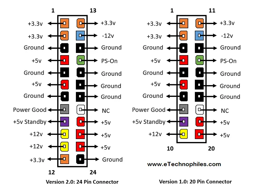
ATX 24-Pin 12V Power Connector Pinout
Mainly there are two versions of ATX power supply connectors: 24-pin and 20-pin connectors. To supply the additional power required by PCI Express slots, the 24-pin main power connector was added to ATX12V 2.0.

Note: The 24-pin power connector contains 4 additional pins as compared to the 20-pin connector. These are Ground, +3.3V, +5V, and +12V.
The table given below shows the description of each pin of the 24-pin ATX connector.
| Sr. No | Color | Purpose | Description |
|---|---|---|---|
| 1 | Black | 0V (Ground) | This is a common(“COM”) ground pin. |
| 2 | Orange | +3.3V | It provides +3.3V |
| 3 | Red | +5V | It provides +5V |
| 4 | Yellow | +12V | It provides +12v |
| 4 | Yellow with black stripe | +12V(2nd rail) | This is present on new PSUs to separate 4-pin connectors for the processor |
| 5 | White | -5V | It provides -5V |
| 6 | Blue | -12V | It provides -12V usually at a very low amperage |
| 7 | Brown(or smaller-gauge orange) | +3.3V sense | It needs to be connected to orange(+3.3V) wires to allow the PSU to detect and regulate the output |
| 8 | Pink(or smaller-gauge red) | +5V sense | It needs to be connected to red(+5V) wires to allow the PSU to detect and regulate the output |
| 9 | Yellow(Small Gauge) | +12V sense | It needs to be connected to yellow(+12v) wires to allow the PSU to detect and regulate the output |
| 10 | Green | PSU On | By connecting this wire to the ground we can pull the green wire which is +5V to low so that PSU will turn ON. |
| 11 | Grey | Power Good | As long as the PSU is producing power within normal parameters, this wire delivers a +5V signal. An LED illuminates when the item is operating properly and can be powered by it. |
| 12 | Purple | +5V standby | Whenever the PSU is powered, it provides +5V. It can power an indicator LED that will illuminate to signal that the device is powered. |
Check also: RS232 Pinout, Definition, Uses, Speed & Baud Rate
FAQs
Is it fine to connect a 24-pin male cable to a 20-pin connector?
It is okay to connect an ATX power supply with a 24-pin main cable to a motherboard with a 20-pin connector. The additional 4 wires on the cable can remain isolated at the connector end.
