Last updated on March 16th, 2024 at 01:39 pm
STM32 Bluepill is a high-performance, breadboard-friendly development board with a bunch of capabilities and a compact design. It has a 32-bit ARM Cortex M3 processor, 64Kbytes of flash memory, and 20 Kbytes of SRAM, all operating at 72MHz.
It offers various peripherals and I/O, including three general-purpose 16-bit timers and one PWM timer, multiple high-resolution ADC, multi-channel Direct Memory Access, and several 16-bit general-purpose timers.
There are 10 analog pins and 37 digital I/O pins on this board out of which 12 pins support pulse width modulation. It also features several communication interfaces, including a CAN, three UARTs, two I2Cs and SPIs, two USBs, and two I2Cs and SPIs. Additionally, it enables the addition of more flash by allowing the board to be soldered with an SPI Flash.
Table of Contents
Board Layout

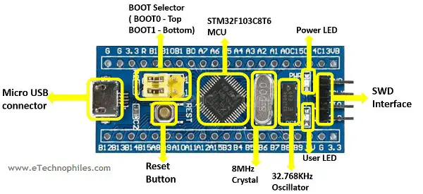
STM32F103C8T6 MCU: It is a 32-bit ARM Cortex-M3 microcontroller in a 48-pin LQFP device. It features a high-performance RISC CPU running at 72MHz, fast embedded memories, a wide variety of improved I/Os, and peripherals coupled to two APB buses. The 12-bit ADC, timers, PWM timer, standard, and advanced communication interfaces are all included in this MCU.
BOOT selector: Using this, we can switch between two boot modes, i.e., BOOT1 and BOOT0.
SWD Interface: This interface is used for programming and debugging using the ST-Link.
8MHz Crystal: The primary STM32 microcontroller makes use of this crystal.
32.768KHz Oscillator: This oscillator is used for the RTC which is a real-time clock
Power Status LED: This LED serves as a power indicator.
Built-in LED: This inbuilt LED is connected to the pin PC13.
Reset button: This is used to reset the board.
MicroUSB connector: Using this we can connect the STM32 board to our PC or Laptop
Arduino UNO vs STM32 Bluepill
Arduino UNO operates at a voltage of 5V while the STM32 operates at 3.3V. At the same time, an Arduino UNO gives a maximum output current of 40mA while the STM32 gives a 6mA output current. More differences are shown in the table below.
| Parameter | ARDUINO UNO | STM32 BluePill |
|---|---|---|
| MCU | ATMEGA328P | STM32F103C8T6 |
| CPU Clock Speed | 16Mhz | 72Mhz |
| Analog pins | 8 | 10 |
| Digital I/O | 14 | 37 |
| PWM Pins | 6 | 12 |
| Flash Memory | 32KB | 64KB/128KB |
| USB Connector | Type B | Micro |
| UART | 1 | 3 |
| SPI | 1 | 2 |
| I2C | 1 | 2 |
| Operating/Input voltage | 5V | 3.3V |
| Max Output Current | 40mA | 6mA |
Pinout

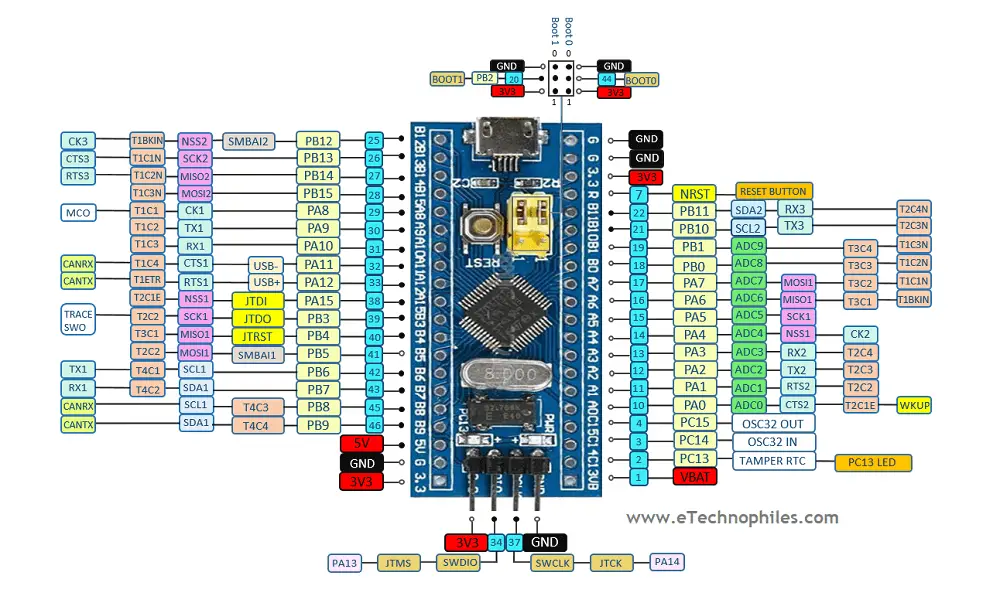
There are 10 analog pins and 37 GPIO pins on this board of which 12 are PWM. It has USB and CAN ports, two popular modern communication interfaces. Because the peripherals operate at a very low voltage and provide excellent board control, they are appropriate for low-power applications. The complete pinout description is provided in the table below.
| S No. | Name | Pin | Description |
| 1 | Input-Output pins | PA0-PA15, PB0-PB15, PC13-PC15 | Total of 37 I/O pins are available |
| 2 | Analog Pins | PA0-PA7, PB0-PB1 | Total 10 analog pins with 12bit resolution are present |
| 3 | External Interrupts | PA0-PA15, PB0-PB15, PC13-PC15 | Interrupt pins |
| 4 | Pulse Width Modulation Pins(PWM) | PA0-PA3, PA6-PA10, PB0-PB1, PB6-PB9 | Total 15 Pulse-width Modulation pins are present |
| 5 | Serial Communication ( UART) | TX1, RX1 – Pin PA9, PA10 TX2, RX2 – Pin PA2, PA3 TX3, RX3 – Pin PB10, PB11 | A total of 3 Serial ports are available |
| 6 | SPI | MOSI1,MISO1,SCK1,NSS1 – Pin PA7,PA6,PA5,PA4 MOSI2,MISO2,SCK2,NSS2 – Pin PB15,PB14,PB13,PB12 | 2 SPI Peripherals are avaliable |
| 7 | CAN | CAN0TX, CAN0RX – Pin PA12, PA11 | 1 Can bus is present |
| 8 | I2C | SDA1,SCL1 – Pin PB7, PB6/ PB9 PB8 SDA2,SCL2 – Pin PB11,PB10 | 2 I2C channels are available |
| 9 | Power | 3.3 Volts 5 Volts GND | 3.3V- Its Supplies 3.3v regulated supply 5V- It supplies 5v regulated supply GND – Ground |
| 10 | Inbuilt LED | PC13 | LED to serve as a universal GPIO indicator. |
Read also: ESP32 Dev board Pinout, Specifications, datasheet, and Schematic
Specifications
The STM32 has 37 digital I/O pins, 10 analog inputs, and operates at a voltage of 3.3V. It has SRAM of 20KB and flash memory of 64/128KB. The highest achievable clock frequency is 72MHz. It has the following modes of communication: I2c, SPI, UART, CAN, and USB.
| Sr. No. | Name | Description |
|---|---|---|
| 1 | MCU | STM32F103C8T6 |
| 2 | Flash Memory | 64/128KB |
| 3 | SRAM | 20KB |
| 4 | Clock Frequency | 72MHz(Max) |
| 5 | Analog inputs | 14 |
| 6 | Digital I/O pins | 37 |
| 7 | PWM Pins | 12 |
| 8 | I2C Peripherals | 2 |
| 9 | SPI Peripherals | 2 |
| 10 | CAN 2.0 Peripheral | 1 |
| 11 | Operating Voltage | 2.7V to 3.6V |
| 12 | Maximum current per pin | 6mA |
Programming Softwares
We can program the STM32 blue-pill development board or STM32F103C8T6 chip using a couple of options. Among them, Arduino IDE is one of the easiest IDE. We can use an embedded C/C++ programming language to program this board. The list of other software is given below:
- Arduino IDE
- STM32 Cube IDE
- Keil ARM MDK
- IAR workbench
- Atollic TrueStudio
- MicroC Pro ARM
- Crossworks ARM
- Ride 7

