Last updated on March 21st, 2024 at 11:46 am
RS232 is a standard for serial communication between devices. It is commonly used to connect computer equipment, although it can also be found in other electronic devices such as TVs and printers.
Table of Contents
What is the RS232 Protocol?
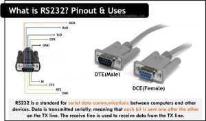
RS232 is a standard for serial data communications between computers and other devices. The protocol uses a simple three-wire interface consisting of a transmit (TX) line, a receive (RX) line, and a ground (GND) line. Data is transmitted serially, meaning that each bit is sent one after the other on the TX line. The receiving line is used to receive data from the TX line.
It was introduced in the 1960s. Back then, RS232 was preferred for connecting computers and Programmable Logic Controllers (PLC) with peripherals such as printers, mice, and modems. But these are now being replaced with modern technologies like Universal Serial Bus (USB).

It is an asynchronous protocol, meaning that it does not require a clock signal to synchronize data transfer. The simplicity of the RS232 interface makes it widely used in a variety of applications including industrial control, barcode scanners, and GPS receivers. It is also commonly used in debugging tools such as JTAG adapters.
Being one of the EIA standards, RS232 is also known as the EIA232 protocol. It is the most commonly used serial communication protocol in the industry.
This protocol has dedicated cable and connector standards to support serial data exchange. Let’s know more about the connector and cable used for RS232.
RS232 connector
RS232 connector is primarily used for serial data exchange between DTE and DCE. This exchange will be usually with the computer and the peripherals.
This protocol was introduced to overcome the limitations caused by the parallel data exchange methods.
As you can see, it is large compared to the other connectors. The old version had 25 pins. This was later reduced to 9 pins which are being used currently.
RS232 cable
The cables provide the necessary electrical connection for the terminals during data transfer. Thus RS232 terminals should not be connected with ordinary cables.
The 9-pin DB9 cables are used to connect with the RS232 standard.
Since the connection is between the DTE and DCE, the pins are assigned a 1:1 order. That means the Nth pin of DTE should be connected to the Nth pin of DCE. Thus, no crossover connection occurs in this protocol.
Speed and baud rate
A reliable data transfer with RS232 protocol is possible only for a distance of up to 20 meters. The speed of asynchronous transmission is up to 20 kbps(15-20meters). Whereas the maximum possible data rate is 1Mbps(very short distance).
As for the baud rate, standards are 9600, 19200, and 38400; for cable lengths up to 20 meters. The higher baud rates may or may not work, but it’s possible. For example, 38400 and 57600 Baud (bits/s).
RS232 Pinout
RS232 protocol uses a 9-pin DB9 connector. The pinout of the male and female RS232 connectors is shown below.


The description and arrangement of male connector pins are given in the table below.
| No. | Name | Description/Signal |
| 1 | DCD | Data Carrier Direct |
| 2 | RxD | Receive Data |
| 3 | TxD | Transmit Data |
| 4 | DTR | Data Terminal Ready |
| 5 | GND | Ground |
| 6 | DSR | Data Set Ready |
| 7 | RTS | Request To Send |
| 8 | CTS | Clear To Send |
| 9 | RI | Ring Indicator |
Similar article: What is RS485 Pinout, 12 Key Advantages & FAQs
These nine pins are divided into three categories:
Data pins– The flow of the data occurs through the data pins. Pins 2 and 3 are the data pins. These are RxD and TxD pins. The DTE and DCE have the interchanged order for data pins.
Control pins– The control pins are used to establish the interface between the devices. Pin 1,4,6,7,8,9 fall under the category of control pins.
Reference pin– The reference pin is meant to be the reference voltage pin. Pin 5 is the reference pin that connects to Ground.
Note: Usually, DTE device(male connector) transmits the signal and DCE device(female connector) receives it. Both the ports have 9 pins. The only difference in their pinout is of the position of transmit and receive pin. The transmit pin in a DTE port is where the receive pin of DCE port is.
What is RS232 used for?
RS232 is mostly utilized in networks with PLCs where a PLC transfers data to other devices using this protocol. In this case, the PLCs act as DTE, and the other devices like printers, modems, etc act as DCE.
Some of the common applications of RS232 in serial communication are:
- Simple full-duplex communication with 2 pins.
- Since it supports asynchronous communication, it can replace the systems that face the difficulty of syncing different clocks.
- It can be used for systems that demand better accuracy.
- It is the best choice to control one unit at a time without delay.
FAQs
What does RS232 stand for?
All EIA standards start with RS. RS stands for Recommended Standard. But the numbers do not carry a specific meaning.
In this case, the number ‘232’ is assigned with ‘RS’ by EIA to denote the serial communication standard. Thus RS232 interface is used for serial communication that transmits binary data for the communication of DTEs and DCEs.
How many wires is RS232?
RS-232 requires a minimum of 3 wires for basic communication: transmit data, receive data, and ground.
What are the mandatory pins for RS232?
RS-232 only needs 3 pins for basic communication: TxD (sends data), RxD (receives data), and GND (common ground). These three are the essential connections for data flow.
What are the advantages of RS-232 over RS-485?
RS-232 has low cost and easy integration with just 3 wires. Its technology and readily available components, make it a good choice for short-distance, low-speed connections between two devices. However, for longer distances, higher data rates, or communication with multiple devices, RS-485 is the superior option.