Last updated on March 14th, 2024 at 05:40 pm
Arduino Nano 33 IoT is one of the four new boards added to the Nano family. And is exceeding all expectations in terms of popularity due to its inbuilt IoT-friendly functionality, with BLE and low power processor.
This board comes with 448 KB of ROM, 520KB SRAM, and 2MB Flash. There are a total of 22 digital I/O pins on the board. Out of these 22 pins, 14 are specific digital pins, 8 are analog pins and 11 can be used for PWM output.
The board comes with a SAMD21 Cortex®-M0+ 32bit low power ARM MCU running at 48 MHz. The inbuilt WiFi and Bluetooth® connectivity features are achieved using a module from u-blox, the NINA-W102. This is a low-power Wireless module operating in the 2.4GHz range.

And just like the Arduino Nano RP2040 Connect, 33 IoT also features a Microchip® ECC608 crypto chip for secure communication. On top of those, it has a 6-axis IMU, LSM6DS3.
Table of Contents
Note: This Arduino Nano 33 IoT board works on 3.3V logic and shall not be considered as a direct replacement for the Arduino Nano. You can use this board as a normal Arduino board but the main purpose of using these new Nano boards is Wi-Fi and Bluetooth connectivity as well as running Machine learning algorithms in your project.Specifications
Technical specifications of Arduino Nano 33 IoT are given below in tabular form.
| Board | Arduino® Nano 33 IoT |
|---|---|
| SKU | ABX00027 |
| Microcontroller | SAMD21 Cortex®-M0+ 32bit low power ARM MCU |
| USB connector | Micro USB |
| Built-in LED Pin | 13 |
| Digital I/O Pins | 14 |
| Analog input pins | 8 |
| PWM pins | 5 |
| External interrupts | All digital pins |
| WiFi | Nina W102 uBlox module |
| Bluetooth | Nina W102 uBlox module |
| IMU | LSM6DS3 |
| Communication | UART, I2C, SPI |
| Circuit operating voltage | 3.3V |
| Input voltage (limit) | 21V |
| DC Current per I/O Pin | 15 mA |
| Clock speed | 48 MHz |
| SAMD21G18A | 256 KB SRAM, 1MB flash |
| Nina W102 uBlox module | 448 KB ROM, 520KB SRAM, 2MB Flash |
| Weight | 5gram |
| Width | 18 mm |
| Length | 45 mm |
Board layout

Note: IoT stands for Internet of Things, meaning the board is suitable for IoT projects and applications. Its main focus is transmitting/receiving data wirelessly while consuming low energy. And 33 in Arduino Nano 33 IoT signifies that the board is compatible with 3.3V IP/OP.
SAMD21 Processor

It comes with the SAMD21 chip, which is a low-power Arm® Cortex®-M0 32-bit CPU clocked at 48 MHZ.
**Download the SAMD21 datasheet from here.
Nina W102 wifi-Bluetooth module

The Nina W102 module provides wifi and Bluetooth connectivity to this Arduino board.
It has its own microcontroller inside, an ESP32 microcontroller\ chip. And gives you full WiFi connectivity based on 802.11b/g/n IEEE standards along with Bluetooth connectivity and BLE v4.2.
Note: The board only works with 2.4 GHz networks as the wi-fi module does not support a 5 GHz network.
ATECC608A Cryptographic IC

ATECC608A is a Cryptographic Co-Processor IC with Secure Hardware-Based Key Storage for up to 16 keys or certificates in its built-in EEPROM.
This IC provides Hardware Support for Symmetric Algorithms of type:
SHA-256 & HMAC Hash including off-chip context save/restore
AES-128: Encrypt/Decrypt, Galois Field Multiply for GCM
LSM6DSOXTR 6-axis IMU or Initial measurement unit

The Arduino Nano RP2040 connect has an inbuilt LSM6DS3 6-axis IMU. This 6-axis IMU provides data from a 3D gyroscope as well as a 3D accelerometer built inside it.
The interesting feature is that it is also possible to do machine learning on the IMU for gesture detection.
RAM and Flash Memory
It comes with 448 KB of ROM, 520KB SRAM, and 2MB Flash.
USB Micro power port
The board comes with a micro USB port that connects it to a PC and also powers the board.
Power LED
The board has a green power LED which indicates the ON/OFF status of the board.
Inbuilt programmable LED
The board has an inbuilt orange LED connected to the digital pin 13.
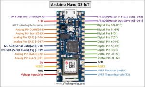
Pinout of Arduino Nano 33 IoT
The Pinout of Arduino Nano 33 IoT shows that there are a total of 22 digital I/O pins on the board. Out of these 22 pins, 14 are specific digital pins, 8 are analog pins and 11 can be used for PWM output. Board has one 5 V, one 3.3 V, two reset, and two Ground pins.

Vin
It is the modulated DC supply voltage, which is used to regulate the ICs used in the connection. It is also called the primary voltage for ICs present on the Arduino board.
Digital Pins
There are 14 digital I/O pins. The Arduino digital pins can read only two states: when there is a voltage signal and when there is no signal. This kind of input is usually called digital (or binary) and these states are referred to as HIGH and LOW or 1 and 0.
PWM Pins
All the digital pins on Arduino Nano 33 BLE sense are PWM (Pulse Width Modulation) enabled pins that are numbered from D0 to D13. Every one of these digital pins can generate a Pulse Width Modulation signal of 23-bit resolution. We can generate the PWM signal using the analogWrite() function in the program.
Analog Pins
The board consists of 8 analog input pins numbered from A0 to A7 while the analog output can only be achieved using PWM pins. This means we can connect up to 8 analog input sensors to the board. The function of Analog pins is to read the value of the analog sensor used in the connection. Each of these analog pins has an inbuilt ADC of resolution of 212 bits.
NOTE: As opposed to other Arduino Nano boards, pins A4 and A5 have an internal pull-up and default to be used as an I2C Bus so using these as analog inputs is not recommended.
I2C Pins

It is the two-wire serial communication protocol. It stands for Inter-Integrated Circuits. The I2C interface uses two pins for communication, to send and receive data: a serial clock pin (SCL) and a serial data (SDA) pin.
- SCL-It stands for Serial Clock. It is defined as the line that transfers the clock data. It is used to synchronize the shift of data between the two devices. The Serial Clock is generated by the master device.
- SDA-It stands for Serial Data. It is defined as the line used by the slave and master to send and receive data. That’s why it is called a data line, while SCL is called a clock line.
I2C Pins on the board: A4(SDA), A5(SCL)
SPI Pins

It stands for Serial Peripheral Interface. It is used by the microcontrollers to communicate with one or more peripheral devices quickly. There are three common pins to all the peripheral devices:
- SCK-It stands for Serial Clock. This pin generates clock pulses, that is used to synchronize the transfer of data.
- MISO-It stands for Master Input/ Slave Output. This data line in the MISO pin is used to send the data to the master.
- MOSI-It stands for Master Output/ Slave Input. This line is used for sending data to the slaves/peripheral devices.
SPI pins on the board: D13(SCK), D12(MISO), D11(MOSI)
RXD and TXD
TXD and RXD pins are used for serial communication. The TXD is used for transmitting the data, and RXD is used for receiving the data during serial communication. It also represents the successful flow of data from the computer to the board.
UART pins: D0(TX), D1(RX)
Other pins
3.3V: The 3.3V pin works as the output-regulated voltage of 3.3V.
Note: Arduino Nano 33 BLE Sense only supports 3.3V logic. So applying 5V logic can damage the board.
5V: The 5V pin outputs 5v to the external components. The power source of 5V for the Arduino Nano board is through the USB connector and the Vin pin.
Note: One more thing to keep in mind is that the 5V pin is disabled by default so you need to bridge the solder jumper at the bottom of the board to enable this pin.
Once enabled, the 5V will directly pass through the USB cable to this pin because there is no onboard 5V regulator.
GND (Ground pins): There is a total of 5 ground pins on the board.
RST: It is used to add a Reset button to the connection.
AREF: This pin stands for analog reference. It provides the voltage reference at which the microcontroller is currently operating. Sending a signal to this pin does nothing.
LED Indicators
Arduino Nano 33 BLE Sense board consists of 4 LED indicators:
Power LED(Green): It indicates that the Arduino board is powered ON.
Programmable LED (Orange): The board also comes with a built-in LED like every other Arduino board that can be programmed accordingly.
Schematic
To download the official schematic of Arduino Nano 33 IoT, CLICK HERE.
Dimensions

Where to buy?
You can get the original Arduino Micro board from different stores. But if you want to get it from Amazon, we recommend the following sellers.
![Arduino Nano 33 IoT [ABX00027] - 32-bit ARM Cortex-M0+, WiFi & Bluetooth, 256KB Flash, 32KB SRAM, Secure Element, 14 Digital I/O Pins, 6 Analog Inputs, Compatible with Arduino IDE for IoT Projects](https://m.media-amazon.com/images/I/4141WeQ85sL.jpg)
FAQs
Does Arduino Nano 33 have WiFi?
The Nano 33 IoT has a WiFi module but Nano BLE has only Bluetooth functionality.
What is the difference between Arduino Nano and Nano 33 ble?
The Arduino Nano and Nano 33 BLE differ in microcontrollers, with the Nano utilizing ATmega328P while the Nano 33 BLE boasts an ARM Cortex-M4 processor with BLE. Connectivity, processing power, and memory also distinguish them, with the Nano 33 BLE offering more advanced features.
What frequency is Arduino Nano 33 IoT?
The Arduino Nano 33 IoT operates on a frequency of 48 MHz.