Last updated on April 5th, 2024 at 11:42 am
HDMI is a very popular audio-visual interfacing standard used in many devices. It enables the transmission of audio and visual data through a single cable with an ultra-high resolution.
Different types of HDMI connectors are now available in the market. Also, the devices incorporate the HDMI port based on convenience in specification and space. Let’s see the pinout diagrams and connections of the most significant HDMI connector types.
Table of Contents
HDMI pinout
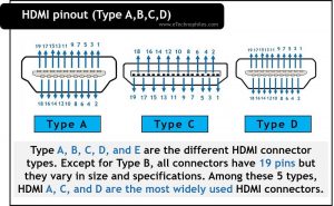
Type A, B, C, D, and E are the different HDMI connector types. Except for Type B, all connectors have 19 pins but they vary in size and specifications. Among these 5 types, HDMI A, C, and D are the most widely used HDMI connectors.
The figure below shows the pinout of the HDMI connector(A, C, D). The 19 pins are allocated as two rows. The numbering starts from the right and progresses alternatively between the top and bottom rows.
Now let’s see how the signaling differs among Type A, C, and D HDMI connectors.
Note: The pinout shown here is of HDMI connectors and not of HDMI ports. Their pinout is identical but exactly opposite of each other i.e, pin 1 of the HDMI connector is pin 19 on the HDMI port.
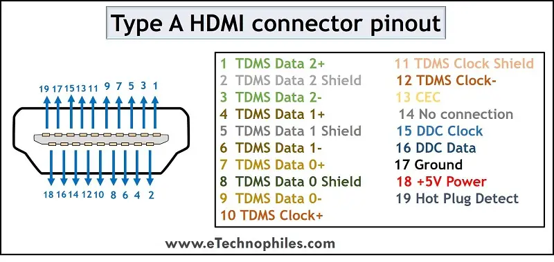
Type A HDMI connector pinout

Type A is the standard HDMI connector. The size of the male connector is 13.9 mm × 4.45 mm and that of the female connector is 14 mm × 4.55 mm. This is the largest connector type. The signal description is given in the table below.
| Pin Number | Signal Name | Pin Number | Signal Name |
|---|---|---|---|
| 1 | TDMS Data 2+ | 11 | TDMS Clock Shield |
| 2 | TDMS Data 2 Shield | 12 | TDMS Clock- |
| 3 | TDMS Data 2- | 13 | CEC |
| 4 | TDMS Data 1+ | 14 | No connection |
| 5 | TDMS Data 1 Shield | 15 | DDC Clock |
| 6 | TDMS Data 1- | 16 | DDC Data |
| 7 | TDMS Data 0+ | 17 | Ground |
| 8 | TDMS Data 0 Shield | 18 | +5V Power |
| 9 | TDMS Data 0- | 19 | Hot Plug Detect |
| 10 | TDMS Clock+ |
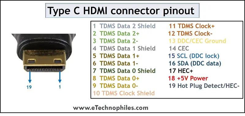
Type C(Mini) HDMI connector pinout

Type C is also called a Mini HDMI Connector. The size of the mini connector is 10.42mm × 2.42mm.
The pin description of the Type C HDMI connector is given below:
| Pin Number | Signal Name | Pin Number | Signal Name |
|---|---|---|---|
| 1 | TDMS Data 2 Shield | 11 | TDMS Clock+ |
| 2 | TDMS Data 2+ | 12 | TDMS Clock- |
| 3 | TDMS Data 2- | 13 | DDC/CEC Ground |
| 4 | TDMS Data 1 Shield | 14 | CEC |
| 5 | TDMS Data 1+ | 15 | SCL (DDC lock) |
| 6 | TDMS Data 1- | 16 | SDA (DDC data) |
| 7 | TDMS Data 0 Shield | 17 | HEC+ |
| 8 | TDMS Data 0+ | 18 | +5V Power |
| 9 | TDMS Data 0- | 19 | Hot Plug Detect/HEC- |
| 10 | TDMS Clock Shield |
Note: The pinout of the mini connector is almost similar to the standard A connector, except for a few changes.
- The positive signal and the corresponding shield signals are swapped in each set.
- Pin 13 is DDC/CEC instead of pin 17
- Pin 14 is CEC instead of 13
- Pin 17 is an additional pin connected to HEC
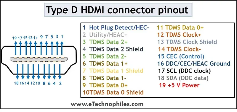
Type D(Micro) HDMI connector pinout

Type D is also called a Micro HDMI Connector. The size of this connector is 5.83 mm x 2.2 mm. This is the smallest HDMI connector.
Although it is the smallest, it also maintains 19 pins and retains all the basic functionalities. However, the order of signaling is slightly different, which is given in the table below.
| Pin Number | Signal Name | Pin Number | Signal Name |
|---|---|---|---|
| 1 | Hot Plug Detect/HEC- | 11 | TDMS Data 0- |
| 2 | Utility/HEAC+ | 12 | TDMS Clock+ |
| 3 | TDMS Data 2+ | 13 | TDMS Clock Shield |
| 4 | TDMS Data 2 Shield | 14 | TDMS Clock- |
| 5 | TDMS Data 2- | 15 | CEC (Control) |
| 6 | TDMS Data 1+ | 16 | DDC/CEC/HEAC Ground |
| 7 | TDMS Data 1 Shield | 17 | SCL (DDC clock) |
| 8 | TDMS Data 1- | 18 | SDA (DDC data) |
| 9 | TDMS Data 0+ | 19 | +5 V Power (power EDID/DDC) |
| 10 | TDMS Data 0 Shield |
Type B HDMI connector pinout
Type B is the Dual-link HDMI connector. To support this extra feature, it has 29 pins while all other connector types have 19 pins. However, this connector was not used in any devices since the newer HDMI version(1.3) does not support this dual link property.
The pinout description of HDMI type B is given in the table below.
| Pin Number | Signal Name | Pin Number | Signal Name |
|---|---|---|---|
| 1 | TDMS Data 2 + | 16 | TDMS Data 4 + |
| 2 | TDMS Data 2 Shield | 17 | TDMS Data 4 Shield |
| 3 | TDMS Data 2 – | 18 | TDMS Data 4 – |
| 4 | TDMS Data 1+ | 19 | TDMS Data 3 + |
| 5 | TDMS Data 1 Shield | 20 | TDMS Data 3 Shield |
| 6 | TDMS Data 1- | 21 | TDMS Data 3 – |
| 7 | TDMS Data 0+ | 22 | CEC |
| 8 | TDMS Data 0 Shield | 23 | Reserved |
| 9 | TDMS Data 0 – | 24 | Reserved |
| 10 | TDMS Clock+ | 25 | SCL |
| 11 | TDMS Clock Shield | 26 | SDA |
| 12 | TDMS Clock- | 27 | DDC/CEC Ground |
| 13 | TDMS Data 5 + | 28 | +5V Power |
| 14 | TDMS Data 5 Shield | 29 | Hot Plug Detect |
| 15 | TDMS Data 5 – |
Pin description of HDMI connector
The pinout description of HDMI connectors has several abbreviations. It is essential to know what they denote for a proper understanding of the signaling of the connectors.
TDMS, CEC, DDC, HEC, HEAC, SCL, SDA, and EDID are the abbreviations included in the pinout. Most of these are different communication channels used in HDMI technology. Let’s see them in detail.
- Transition Minimized Differential Signaling (TMDS) The HDMI cable carries three (six, in the case of Type B) TDMS data channels numbered 0, 1, and 2. These channels are meant for the transmission of video, audio, and auxiliary data as separate packet types.
- Consumer Electronics Control (CEC) This channel is meant for the command and control of the user for up to 15 devices.
- Display Data Channel (DDC) This channel is meant for communication between the display monitor and the PC. DDC communication is based on I2C (Inter-Integrated Circuit) bus specification.
- HDMI Ethernet Channel (HEC) The channel allows the devices connected to HDMI to access the internet without using separate Ethernet cables. It is transmitted as a differential signal.
- HDMI Ethernet and Audio Return Channel (HEAC) It was introduced in HDMI 1.4. This channel is used for high-speed bi-directional data communication. It used two pins of the connector: an unused pin and the hot plug-detecting pin
- I2C Serial Clock for DDC (SCL)
- I2C Serial Data for DDC (SDL)
- Extended Display Identification (EDID) It is a signal transmission standard that enables the display devices to communicate with the video source.

hi there
im trying to rig my own type A to type D hdmi i cable. is it a straight forward soldering job or is there special wiring needed between the two? your advice will be greatly appreciated. thanks
I don’t think there’s much of an issue here, apart from the fact that soldering them together is a very complex task. But if you’re experienced, you should definitely give it a try 🙂