Last updated on April 5th, 2024 at 11:45 am
USBs have become a vital part of our day-to-day life. The wide range of applications includes interfacing, power delivery, data storage, and many more. USBs are available in numerous standards, types, and sizes to meet the varying requirements of the industry. USB C is in the top demand in this category. In this article, we will discuss the features and pinout of USB C.
Table of Contents
Features of USB C
- It was launched in August 2004 by the USB Implementers Forum (USB-IF).
- It supports high-speed data transfer up to 10Gbps and can handle up to 5A current and 100W power.
- The greatest advantage of USB C is that it is a rotationally symmetric connector.
That is, we don’t need to bother about the direction of inserting it into the port. Hence it is more popular among devices for data transmission and power delivery.
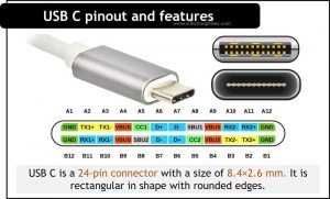
USB C Pinout

USB C is a 24-pin connector with a size of 8.4×2.6 mm. It is rectangular with rounded edges. The pinout diagram of the USB C connector is shown in the figure below.
Since USB C is rotationally symmetric, the pin allocation for the male and female connectors remains the same. The pinout description is listed in the table below.
| Pin | Description | Pin | Description |
| A1 | Ground | B12 | Ground |
| A2 | Superspeed differential pair 1, TX, positive | B11 | Superspeed differential pair 2, RX, positive |
| A3 | Superspeed differential pair 1, TX, negative | B10 | Superspeed differential pair 2, RX, negative |
| A4 | Bus power | B9 | Bus power |
| A5 | Configuration channel | B8 | Side Band Use (SBU) |
| A6 | Differential pair 1, positive | B7 | Differential pair 2, negative |
| A7 | Differential pair 1, negative | B6 | Differential pair 2, positive |
| A8 | Side Band Use (SBU) | B5 | Configuration channel |
| A9 | Bus power | B4 | Bus power |
| A10 | Superspeed differential pair 4, RX, negative | B3 | Superspeed differential pair 3, TX, negative |
| A11 | Superspeed differential pair 4, RX, positive | B2 | Superspeed differential pair 3, TX, positive |
| A12 | Ground | B1 | Ground |
Pin Description
Among the 24 pins, there are:
- two pairs of ground pins(GND)
- two pairs of power pins(VBUS)
- two differential pairs(D+ and D-)
- four shielded differential pairs(two sets of TX and RX).
- SBU and CC pins are two special-purpose pins in the connector.
Let’s understand it in a bit more detail.
VBUS and GND pins
One pair of GND pins are located at either end of the connector. VBUS pins allow power delivery with a voltage of up to 20V, but the default voltage of VBUS is 5V.
D+ and D- pins
D+ and D- pins are used from USB 2.0 standards for high-speed data transmission. There are two pairs of D+ and D- pins which are located at the center of the connector.
TX and RX pins
The two sets and TX and RX pins are meant for Enhanced super-speed data transmission.
CC
CC stands for channel configuration. The single pair of channel configuration pins handles functions such as plug orientation detection, current advertisement, cable attachment, and removal detection and also manages the communication between Power Delivery and Alternate Mode.
SBU
The SBU pair is used at low-speed signal paths while working in Alternate Mode.
The Alternate mode is an enhanced feature employed by USB 2.0. It incorporates third-party protocols like DisplayPort and HDMI using USB C.
FAQs
Which pins on USB-C are power?
The VBUS pin delivers power, ranging from 5V to 20V, through a USB-C connector. The GND pin acts as the ground reference. Together, they facilitate power transmission to connected devices, enabling efficient charging and operation.
What are the 3 wires in A USB-C cable?
The three standard wires that a USB-C cable consists are:
1. VBUS (Voltage Bus): This wire carries the power supply.
2. D+ and D- (Data Positive and Data Negative): These wires are used for data transmission.
3. GND (Ground): This wire serves as the reference voltage and completes the circuit.
Does USB-C use all 24 pins?
No, USB-C doesn’t use all 24 pins simultaneously. The number of pins used depends on the specific functions and protocols being utilized, such as data transfer, power delivery, video output, and audio output. Different functionalities may require different pin configurations within the USB-C connector.
What is a Type-C female?
A Type-C female refers to a USB-C connector socket or port that is designed to accept a USB-C plug. The Type-C female connector allows for reversible insertion of the USB-C plug, making it easier to connect devices.