Last updated on March 23rd, 2024 at 12:28 pm
You might have seen an electrical transformer installed over your nearest electricity pole, or you might have seen one in an electricity generation or distribution station. But, have you ever thought about why we need it? Why do we use it? And how does it look from the inside? Well, if you are still searching for the answers, then you’ve crashed into the correct place. This blog will clear all your doubts about the electrical transformer.
So, let’s start our discussion on the electrical transformer with some basics.
Table of Contents
What is an electrical transformer?

A transformer is a static device that transfers electrical energy between two alternating circuits via a magnetic circuit. It is an essential part of the power system that meets two purposes:
- Voltage transformation:
A transformer’s prime role is to either increase the voltage level (step-up) or decrease the voltage level (step-down) in an electrical system.
- Isolation:
An electrical transformer isolates the output load from the power source. The isolation protects against electric surges and suppresses electrical noise.
History of transformer
Before diving a bit deep into the transformers, let us see their origins.
The credit for the discovery of Electromagnetic induction goes to Michael Faraday. In 1891, he gave an equation describing the relationship between the EMF and magnetic flux, known as Faraday’s law of Electromagnetic induction.

In 1876, Pavel Yablochkov invented a set of induction coils for a lighting system. It can be considered a typical open-core transformer as the primary side was connected to an AC source while the secondary side, to homemade arc lamps.
But the credit for giving us the first electrical transformer goes to three Hungarian engineers, namely Karoly Zipernowsky, Otto Blathy, and Miksa Deri. In 1884, they found that closed-core transformers were more efficient in regulating the voltage than open-core ones and proposed two designs.

Their designs involved a closed magnetic circuit with a copper wire wound around an iron wire core.
It was the earliest design of a shell-type transformer. So, after these many years, let’s see how a modern-day transformer looks from the inside.
Construction of an electrical transformer
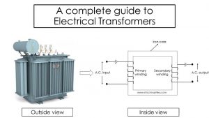
The simplest form of the transformer consists of copper windings and an iron core. As visible in the figure below, the iron core consists of a set of windings on both limbs.

The winding that connects to an AC source is known as the Primary winding, while the other one connects to an electrical load (e.g., AC motor) and is known as the secondary winding.
Depending on the voltage level, the number of turns in the winding on either limb can be equal or different. So, based on the application, a particular transformer can either be one of the following:
Step-down transformer
A step-down transformer reduces the voltage level. The voltage level on the primary side is more than the voltage level on the secondary side. To maintain the power balance on both sides, the magnitude of current on the secondary side remains more as compared to the primary side.

Step-up transformer
The role of this transformer is to increase the voltage level. So, the voltage level on the secondary side is more than on the primary side.
In a step-up transformer, the converse happens for the flow of current. So, the magnitude of current flowing on the primary side is more than that on the secondary side. Hence, the power remains conserved.

From this discussion, we can conclude two relations:
- The EMF across a winding is directly proportional to the number of turns in that winding.
- The current flowing through a winding is inversely proportional to the number of turns in that winding.
Working principle of transformer
An electrical transformer works on the principle of mutual induction. It states that the flux associated with a coil induces a voltage in the other coil placed close to it.

So, from this principle, it is clear that two sets of copper coils are necessary to build a transformer. But why do we require an iron core?
There are a couple of reasons to use an iron core in a transformer.
- First of all, it supports both sets of windings.
- Secondly, (and most important), the iron core provides a path for the flux to link from the primary winding to the secondary winding.
- Using an iron core instead of air or any other material reduces the losses and allows an easy energy exchange between the circuits.
After an inside view of the electrical transformer, let’s see how the energy transfers between the circuits.
Working of electrical transformer
Consider an iron core with two sets of windings on both of its limbs, as shown in the figure.
When we connect the primary winding to a source of AC supply, the current flowing through the coil produces a magnetic field around it. This flux links with the iron core, and the flux starts circulating in the iron core. As the permeability of the iron core is around 1000 times more than the air around it, the magnetic flux remains in the iron core.

While circulating, when the magnetic flux reaches the other limb, it links with the secondary winding of the transformer. According to Faraday’s law, this process induces an EMF (Electromotive Force) in the secondary winding. If we connect an electrical load on this secondary side, e.g., an AC motor (Induction motor or Synchronous motor), the current starts flowing in this circuit.
Types of the electrical transformer (based on the core used)
There are two types of iron cores used in an electrical transformer. These are the core type and the shell type.
Core-type transformer
The core-type transformer is similar to the one we discussed above. But, there are some changes.
It consists of a rectangular iron core with two limbs. Each limb consists of both primary and secondary windings. Consider one of them the low voltage winding while the other one the high voltage winding.

*Image courtesy: Wikipedia
First of all, the low voltage winding is wrapped equally on both limbs of the transformer. An appropriate insulating layer lies between the iron core and the low-voltage winding. It avoids a short circuit between them.
After that, the high-voltage winding is wrapped equally over the low-voltage winding. Here also, sufficient insulation lies between both the windings.
This construction makes a transformer economical. Wrapping the low voltage winding before the high voltage winding in the transformer reduces the insulating layer thickness. Thus, reducing the cost.
Shell-type transformer
The shell-type transformer is a little bit different as compared to the core-type transformer.
It consists of a rectangular iron core with three limbs.

Here, only the central limb contains both windings. The outer limbs of the core do not carry any winding. The order of wrapping the winding is a bit different in this case.
The high voltage winding lies between the low voltage windings. The wrapping looks similar to a sandwich. First of all, half of the low-voltage winding covers the central limb. Over it lies the complete high-voltage winding. And at the top lies the rest of the low-voltage winding.
This construction is a bit complex, but it decreases the core losses of the transformer. So, the output and efficiency of this transformer are more as compared to the core-type transformer.
Applications of electrical transformer
- Transformers are an essential part of the electrical system that increases or decreases the voltage level depending on their application.
- The impedance-matching property of the transformer allows it to transfer the maximum power from the source to the load. For this unique property, various communication devices require a transformer.
- Isolation transformers provide electrical isolation between two electric circuits. In an isolation transformer, the number of turns in both windings is equal.