Last updated on July 8th, 2021 at 11:19 am
An Induction motor is the most widely used AC motor in industrial and domestic applications. Now you might think, why is it so? It is because of the low cost, simple and rugged construction of the motor. Moreover, it has good operating characteristics with an efficiency as high as 90%. An induction motor does not have any commutator, like the one we saw in a DC motor. Hence it provides a good speed regulation without any sparking.
So, with that many advantages, it becomes essential to meet the mechanical power demand using an induction motor. But doesn’t it makes you wonder that how does this motor work and gives that many advantages? If yes, then stick with this article to grasp every detail on the induction motor.
Construction of an Induction Motor
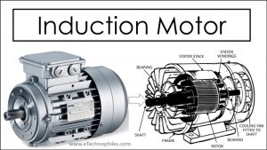
An Induction motor consists of a frame, stator core, rotor, shafts, and bearings.
Frame

It is the outer body of the motor. It supports the stator core and protects the inner parts of the machine from the surroundings.
Stator core
A stator consists of a stack of laminations of silicon steel in the form of a ring. It fits inside the stator frame and contains slots on its inner periphery. These slots carry the three-phase winding, separated by 120 degrees in space. Right here, the figure shows the distribution of three-phase winding in a stator.

Rotor
A rotor consists of a stack of laminations in the form of a cylinder. It has slots punched on its outer periphery, which contains rotor windings. Based on the winding type, there are two categories of rotors.
Squirrel cage rotor

**Image courtesy: Wikipedia
This rotor uses copper or aluminum bars as the rotor conductors. Each slot of the rotor carries a conductor without any insulation from the core. All the conductors are shorted by annular rings, aka end rings.
Wound rotor

It uses wires or straps for the rotor windings. The distribution of the three-phase winding on the rotor is similar to that of the stator. The winding connects to an external resistance through slip rings and brushes. The wound rotor provides a higher starting torque as compared to the squirrel cage rotor.
Shafts and bearings

The induction motor uses ball-and-roller bearings. These bearings support the rotor shaft and make it rotate smoothly.
Induction motor working principle
The induction motor follows these two laws to generate a unidirectional torque.
Faraday’s law of electromagnetic induction
It states that a conductor placed in a varying magnetic field induces an Electromagnetic force (EMF). The closed conductor leads to the flow of current, known as induced current.
Lorentz force law
It states that a current-carrying conductor placed in a magnetic field experiences a force. The force on the conductor is orthogonal to the direction of the current and magnetic field.
Before understanding how these laws govern the rotation of an induction motor, let us see how the stator creates a rotating magnetic field.
The concept of rotating magnetic field
The creation of a rotating magnetic field requires two essential conditions:
- A three-phase distributed winding. The axis of the windings must make a space angle of 120 degrees.
- A three-phase AC source. The magnitude of current in the three phases is equal but is displaced in time by 120 degrees. The figure here shows a sinusoidal wave of a three-phase source. See how each phase current achieves its peak value at different times.

**Image courtesy: Wikipedia
When we give this three-phase supply to the stator windings, the windings start creating a magnetic flux. The figure below shows the orientation of magnetic flux by the three phases after giving a three-phase supply.

But as the current from the three-phase source achieves its peak value at different instant of time, the magnetic flux will follow the same behavior. Let us see how. Consider these time instants X, Y, and Z in the waveform.

Magnetic field vector orientation at selected instants
At point X
At point X, the current magnitude in phase A is more compared to phases B and C. Moreover, the Phase A current is positive, while the current in Phases B and C is negative. So, if we represent the magnetic field vectors at point X, it looks like this. Note the direction of the resultant magnetic field.

At point Y
At point Y, the current magnitude in phase B is more as well as positive. The figure below shows the orientation of the magnetic field vectors at point Y. In this case, the direction of the resultant magnetic field has changed.

At point Z
At point Z, the current magnitude in phase C is more and positive. The vector representation of the magnetic field looks like this. Note that the direction of the resultant magnetic field has again changed.

From the above three time instants, we conclude that the resultant magnitude of the magnetic field always remains uniform, but its direction changes periodically. On tracing the trajectory of the magnetic field vector, we obtain a circle.
Hence, the application of three-phase current to the three-phase distributed winding creates a rotating magnetic field. The field rotates with a constant speed known as synchronous speed.
How does the rotor rotate in an Induction motor?
So, after the generation of the rotating magnetic field, the rotor conductors start interacting with the magnetic field. Assume a rotor conductor interacting with the magnetic field as shown in the figure.

This interaction induces a current in the conductor (according to Faraday’s law of electromagnetic induction). Now, according to Lorentz law, a force starts acting on the conductor. This force tends to displace the rotor in a direction, as shown in the figure.

And the rotor slowly begins to accelerate and try to attain the stator’s synchronous speed.
From this, we conclude that the induction motor is self-starting and requires only a single excitation source.
What happens if the rotor attains the synchronous speed?
So, when the rotor starts rotating, a wide relative speed lies between the stator’s magnetic field and the rotor conductors. As the rotor accelerates, this relative speed starts decreasing. Hence, the current in the rotor conductor starts reducing.
Now, assume that the relative speed between them becomes zero, and the rotor starts rotating with synchronous speed. As this happens, the magnetic field no longer interacts with the rotor conductors. And hence, no current flows in the rotor conductors. As a consequence, no force acts on the rotor conductors. So, the rotor speed will get reduced. The rotor always tries to catch the synchronous speed but never attains it.
Thus we conclude that an induction motor always runs at a lesser Speed than synchronous speed. Hence it is also known as the Asynchronous motor.
What is Slip?
So, we saw that there always lies a speed difference between the rotating magnetic field and the rotor conductors. This speed difference is known as Slip. If we denote the synchronous speed with (Ns) and the rotor speed with (Nr), then the Slip (s) is given by
s = (Ns – Nr)/Ns.
The value of the Slip always ranges between 0 and 1.
Advantages of Induction Motor
- The induction motors are robust. Hence, its working is independent of the external environment conditions.
- They have high starting torque as compared to synchronous motors.
- The induction motor is self-starting. Hence no starting methods are required, unlike synchronous motors.
- The squirrel cage induction motor does not require a commutator, brushes, and slip rings. It eliminates the sparking issues and reduces the overall motor cost.
Disadvantages of Induction motor
- The high-capacity induction motors require a starter for the motor’s smooth operation. The starter reduces the motor’s input current to a safe value which would otherwise have created a voltage drop in the system.
- The induction motor operates at a lagging power factor under lightly loaded conditions. Hence it requires power factor correction devices.
- The speed control of the Induction motor is a bit challenging. Instead, for a wide range of speed control, DC motors are preferred.
**To know the differences between an Induction and a Synchronous motor, read this article: Difference between Induction and Synchronous motor
**To know about other types of AC motor, read this article: Types of AC Motors
Read similar articles:
|DC Motor Working Principle, Construction and Diagram Explanation
|DC Generator Working Principle, Construction and Diagram Explanation