Last updated on February 11th, 2026 at 10:04 pm
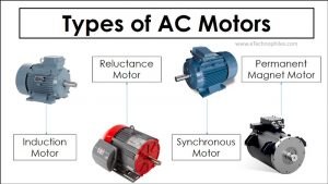
An AC motor requires an AC input to produce a rotating magnetic field. This field interacts with rotor conductors and makes it rotate with the stator field. The two main types of AC motors are Induction motors and Synchronous motors. The figure below shows a detailed explanation of AC motors.

Let us start our discussion on the types of AC motors, with an Induction motor.
Table of Contents
Induction motor

An Induction motor works on the mutual induction principle and transfers the power generated by the Stator to the Rotor. Their(stator and rotor) magnetic fields interact in a way to create a unidirectional torque for the Rotor.
Induction motors are also known as asynchronous motors because they run at a lesser speed than the synchronous speed of the rotating magnetic field.
Induction Motor classification based on the Rotor Winding:
Based on the rotor winding, we have two types of Rotor. i.e., Squirrel cage Rotor and Wound Rotor.
Squirrel cage rotor:

**Image courtesy: Wikipedia
The squirrel cage Rotor uses copper, brass, or aluminum conductors as the Rotor conductors. These conductors rest in the slots of a cylindrical laminated iron core, aka Rotor structure.
To create a path for rotor current, these conductors are shorted at the end using continuous rings, aka End rings.
To obtain a uniform torque and reduce the magnetic locking of the Stator and Rotor, the rotor slots are not made parallel to the motor shaft. Skewing them by an angle also reduces the humming noise while running.
Wound rotor:

This type of Rotor uses a bar, strap, or wire for Rotor windings. Here, the winding is similar to that of the Stator structure.
To increase the Rotor resistance, this Rotor uses an external resistance circuit. For a high starting torque, the entire external Resistance adds to the Rotor circuit. This Resistance gradually cuts out as the motor picks up speed. The slip rings and brushes inside the motor give a connection to the external Resistance. Hence these motors are called slip-ring induction motors.
Induction Motor classification based on the number of phases:
Based on the number of phases, there are two types of AC Induction motors: Single-phase and Three-phase induction motors.
Single-phase induction motor:
These AC motors require only one phase (i.e., one live wire and one neutral wire) of incoming AC supply to operate. It is efficient and economical to meet the demand of small power requiring loads in houses and offices via a single-phase induction motor.
But due to only one phase of AC supply, the Stator does not create a rotating magnetic field, and hence, a single-phase induction motor is not self-starting. It requires an additional winding (aka auxiliary winding) placed orthogonally to the primary Stator winding to make the Rotor rotate.
Single-phase Induction Motor classification based on starting method:
Based on the starting methods, we have five types of AC induction motors: These include Resistance-Start motor, Capacitor-start motor, Capacitor-start-capacitor-run motor, Permanent capacitor motor, and Shaded pole motor.
Resistance-start motor:

Here, the auxiliary winding consists of a Resistance of high value. The difference in the Resistance of the two windings creates a phase difference that rotates the Rotor. A centrifugal switch disconnects the auxiliary winding as the motor achieves 70-80% of synchronous speed.
Capacitor-start motor

This method uses an electrolytic capacitor in the auxiliary winding. It is an improved form of the Resistance-start motor, as it creates a better phase difference between the winding current. A centrifugal switch disconnects the auxiliary winding as the speed of the motor increases.
Capacitor-start-capacitor-run motor

It is similar to the above motor, except the capacitor here remains connected at all times. To attain optimum torque and smooth-running, it uses two capacitors instead of one. A centrifugal switch switches between them once the motor picks 75% of the synchronous speed.
Permanent Capacitor Motor

It is also known as a single value capacitor-run motor. Here the capacitor remains energized all the time and has no centrifugal switch. The rotating field developed in this motor is more uniform as compared to the above methods. It gives a higher operation efficiency and a higher power factor.
Shaded pole motor:

In this motor, around 25% of the stator pole is wrapped by a copper strap, forming a closed-loop, known as shading coil.
When the Stator gets energized, the shading coil causes the flux to shift from unshaded portion to shaded portion. This shifting is like a weak rotating field that makes the rotor move. This method is only suitable for low-power applications.
Three-phase Induction motor
These motors require a three-phase AC supply (three live wires and one neutral wire, or three live wires only) for their operation.
The three wires carry the current of the same magnitude but with a phase difference between them. This phase difference creates a rotating magnetic field for the Stator, and hence there is no need for any starting method.
The industries use massive machines that require more power. A single-phase motor can’t supply enough power for heavy loads. So, using a three-phase electric motor for heavy loads gives a higher power factor and good efficiency.
That was all about the Induction motor types. Now let’s discuss the second type of AC Motor i.e., Synchronous Motor:
Synchronous motor

**Image courtesy: engineering solutions
Unlike induction motors, synchronous motors are not self-starting. The Rotor of the synchronous motor requires a separate energization.
The Stator requires an AC supply to create a rotating magnetic field, while the Rotor either requires a DC supply or an external stator field for its excitation. The Rotor acting as an electromagnet runs in synchronism with the rotating magnetic field of the Stator.
Despite the load variations, the motor always runs at synchronous speed.
Based on Rotor magnetization, there are two types of AC synchronous motors: Non-excited Synchronous motor and Direct current excited Synchronous motor.
Non-excited Synchronous Motor
The non-excited synchronous motor does not require any excitation but uses high retentivity steel to make the Rotor structure.
The Stator field magnetizes the Rotor, and hence, it runs at synchronous speed. We have three types of non-excited AC Synchronous motors. Hysteresis motor, Reluctance motor, and Permanent magnet motor.
Hysteresis Motor:

It uses a cylindrical rotor made of hard cobalt steel. The Rotor starts rotating with a slip as soon as it experiences the Stator’s magnetic field. On attaining the synchronous speed, the Rotor aligns itself with the Stator field. Hence, creating a magnetic lock between the rotating field and the Rotor.
Reluctance Motor:

The Rotor of the reluctance motor consists of a solid steel casing with outward projecting heads (aka salient poles).
Due to this structure, a non-uniform reluctance forms in the air gap. The Rotor always tries to align itself from a more reluctance position to a low reluctance position. Hence, creating a torque that makes the Rotor rotate unidirectionally.
Permanent magnet motor:

It uses a permanent magnet as the Rotor to create a constant magnetic field. The rotor poles magnetically lock with the Stator poles and rotate at synchronous speed.
Direct current excited Synchronous motor

In this method, the Rotor is excited via a DC supply. On excitation, the Rotor acts as an electromagnet. As this motor is not self-starting, it requires damper windings to break the resting inertia. Once the Rotor rotates, the fields of Stator and Rotor align to create a magnetic coupling between them, and the Rotor continues to run with synchronous speed.