Last updated on June 9th, 2021 at 06:29 pm
A DC generator converts mechanical energy to electrical energy. The working of the DC generator is based on Faraday’s Law of Electromagnetic Induction. As the name suggests, the output obtained is DC (Direct current), where the magnitude of current or voltage is constant with time.

The DC output is utilized in field excitation of alternators, series arc lighting, battery charging, driving DC locomotives, or used as boosters to compensate for the voltage drop in the DC distribution system.
CONSTRUCTION OF DC GENERATOR

The construction of a DC generator is similar to a DC motor. So, a DC generator can work as a DC motor and vice-versa. The basic constructional features of a DC generator are described below.
YOKE:
The yoke is the outer covering of the DC generator and is made of cast steel or cast iron. It serves two purposes:
1) Provides a path for pole flux.
2) Provides mechanical support to the whole machine.
FIELD POLES:
It consists of pole core and pole shoes. The pole core supports the field winding while the pole shoe distributes the flux in the air gap uniformly.
FIELD WINDING:
It is made of copper and wound around each pole core in such a way that adjacent North and South poles develop when the field winding is excited.

ARMATURE CORE:
The armature is the center of electromechanical conversion. It is the rotating part of the DC machine and consists of grooves or slots over the entire periphery. These slots carry the current-carrying armature conductors. The armature core is made up of thin laminations to reduce eddy current losses.

ARMATURE WINDING:
Armature winding is made of copper and placed inside the slots of the armature core. Each conductor in the winding is insulated from each other and also from the armature core. The armature winding is of two types: lap winding and wave winding.

COMMUTATOR
A commutator is also known as a mechanical rectifier. It provides an electrical connection between the rotating armature coil and the stationary external circuit. It consists of hard-drawn copper segments insulated from each other forming a ring structure. In a dc generator, the commutator collects the current generated in the armature winding.
BRUSHES
The brushes are either made of carbon, electro graphite, or copper graphite. They always slide over the commutator, thus ensuring a proper electrical connection. Their main function is to collect current from the commutator and supply it to the electrical load or external circuit.

**Read also: Working principle of an AC Motor
WORKING OF DC GENERATOR
As mentioned above, the working of DC Generator is based on Faraday’s law. It states that whenever a conductor cuts magnetic flux, an EMF (Electromotive Force) is induced across the conductor. The magnitude of this induced EMF is directly proportional to the rate of change of flux linkage.
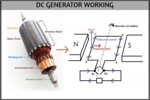
To understand how EMF gets induced in a conductor, let us consider a single-turn rectangular loop ABCD rotating in a clockwise direction between the poles.
CASE 1:
At any instant of time, the conductor AB is close to the North Pole and CD to the South Pole as shown in the figure below.

For conductor AB, the magnetic field is from left to right while the force on it is acting upwards. Now, to find the direction of the induced current, we will use Fleming’s right-hand rule.

“If the thumb, forefinger, and middle finger of the right hand are stretched out and placed mutually perpendicular to each other in such a way that the thumb represents the direction of force, the forefinger represents the direction of the magnetic field, then the middle finger will give the direction of induced current.”
After applying the above rule to the conductor AB, the direction of the induced current is from A to B in the loop ABCD. This current flows externally from brush B2 to B1 powering the load on its way.

CASE 2:
After 180 degrees rotation of the coil, the conductor CD comes close to the North Pole while AB is near to the South Pole.
On applying Fleming’s right-hand rule to conductor CD, the direction of the induced current is from D to C. Although the direction of the current in the loop ABCD is reversed now, the external current still flows from brush B2 to B1.

So in both cases, the direction of the generated current is always from B2 to B1. Hence, a unidirectional current is obtained in the DC generator.
TYPES OF DC GENERATOR:
DC generators are broadly classified into two categories:
Separately excited DC generator
In this type, the field winding is excited from an independent external dc source, such as a battery.
Self-Excited DC generator
In this type, the field winding is excited by the current supplied by the generator itself. A small amount of flux called ‘residual flux’ is initially present in the poles of the generator. As the current increases, the flux increases, which leads to the voltage build-up process in the generator.
According to the connection of the field coil and armature coil, the self-excited generators are classified into three types:
Series Wound Generators:
Here, the field winding is connected in series with the armature winding.
Shunt Wound Generators:
Here, the field winding is connected in parallel to the armature winding.
Compound Wound Generator:
It has two separate field windings. According to the connection of the field winding with armature winding, it can either be a short shunt or long shunt compound wound generator.
REFERENCES:
DC Generator construction: Javapoint
Field poles and Field windings: Muniracademy
Armature Core: Quora
Armature parts of DC Generator: Graschopp
Commutator and brush assembly: Pinterest
Read similar articles:
|DC Motor Working Principle, Construction and Diagram Explanation