Last updated on December 25th, 2024 at 04:55 pm
It’s very important to know about the DC motor working principle and construction in order to master the basics of DC machines. A DC motor converts electrical energy into mechanical energy. The input electrical energy is obtained from rechargeable batteries, solar cells, etc. The mechanical energy generated is further utilized to rotate pumps, fans, compressors, wheels, etc.
Generally, A.C motors are preferred widely in industries. But when it comes to high starting torque or efficient speed control DC motors are the optimal choice. They are used in aluminum rolling mills, electric elevators, railroad locomotives, and large earth-moving equipment.
Table of Contents
DC motor working principle:
The DC motor working principle is that a current-carrying conductor experiences a mechanical force when placed in a magnetic field. This is known as the Lorentz force. The direction of this force is given by FLEMING’S LEFT-HAND RULE.
DC motor working principle is similar to the working principle of a DC generator.
FLEMING’S LEFT-HAND RULE
If you stretch the index finger, middle finger, and thumb of the left hand mutually perpendicular to each other. If the index finger indicates the direction of the magnetic field, the middle finger indicates the direction of current through the conductor, then the thumb will indicate the direction of force acting on the conductor.

**Read also: Working principle of an AC Motor
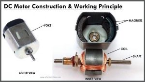
Construction of the DC motor
All DC machines mainly consist of two parts. One is the stator and the other is the Rotor. The stator is a stationary part that includes a yoke, pole, pole winding, and Interpoles. The stator produces the magnetic flux.
The rotor of the DC machine consists of a commutator, brushes, compensating winding, and a shaft. It rotates in external magnetic flux(produced by the stator) when the current flows in it.

Parts of the Stator
Yoke
The yoke or outer frame provides coverage to a DC motor. It is made up of cast steel for large DC motors. And cast iron for small DC motors. The yoke is used in DC machines because:
A) It provides mechanical support to poles.
B) Acts as a protective cover against mechanical damage.
C) And provides a passage for the magnetic flux produced by the poles of the machine.

Pole core and Pole shoe
Both pole core and pole shoes are made of cast steel. But pole shoes are laminated as they are close to the armature.
If the load changes during the operation of the DC motor, the armature current changes. As a result the magnetic flux also changes. This flux links the pole shoe and causes eddy current to flow. To minimize these eddy currents, pole shoes are laminated.
The main purpose of the pole shoe is to spread the flux and reduce the reluctance of the magnetic path. Whereas the pole core is excited with field winding and used to support them.

Pole winding or field coils
The pole winding or field coils consist of copper wire placed in position around the pole core. When current passes through these coils, they electro-magnetize the pole which produces the magnetic flux. This flux passes through the rotor and produces a rotating torque as soon as the current starts flowing in the armature of the rotor.

Parts of Rotor
Armature core
The armature core is the rotating part of a DC/AC machine. It is made up of silicon steel. The cylindrical structure is laminated to reduce the eddy current loss. Its main purpose is to offer a low reluctance path to the magnetic flux. And to house the armature conductors.
Armature winding
Armature winding is composed of coils embedded in armature core slots. These coils are lined next to each other with tough insulating material. The insulating material prevents the two adjacent coils from a short circuit.
Whereas the slot insulation is folded over the armature conductor and is secured firmly by wood or Fibre wedges. In simple words, it is an arrangement of current-carrying conductors that produce EMF in the machine due to relative motion between the windings and the main field.

Commutator
The commutator contains wedge-shaped hard-drawn copper segments, forming a cylindrical structure. A thin sheet of high-quality mica insulates the segments from each other.
A commutator periodically changes the direction of the current between the rotor and the external circuit. Hence, it acts as a switch causing a unidirectional torque in the DC motor.

Brushes
Brushes are usually made of rectangular carbon blocks housed in brush holders. The function of brushes in DC motors is to supply the current to the commutator from an external DC source.
The function of the brushes in a DC generator is to collect the current from the commutator and supply it to the external load circuit.
#/media/File:Carbon_brushes.jpg)
Working of DC motor
The working principle of a DC motor requires magnetic flux and a current-carrying conductor. Consider a coil carrying DC current through a commutator and brushes. These commutator segments rotate freely about their axis.

The commutator segment which comes in contact with the left brush gets positive polarity while the right one gets negative polarity. This leads to the flow of current in the coil.
By applying Fleming’s Left-Hand Rule, the conductor on the left side always experiences a force in an upward direction while the conductor on the right side experiences a downward force. Hence, a unidirectional torque is achieved in DC motors.
Back EMF
The interaction of the current-carrying conductor with the changing magnetic field produced by the field winding induces an EMF in the conductor. This EMF acts in the opposite direction to the applied voltage. This induced EMF in the motor is known as BACK EMF.
Some simple DC motor Projects:
Thank you so much we are learning a lot