Last updated on March 26th, 2024 at 06:12 pm
BC547 is an NPN bipolar junction transistor used in electronic circuits for amplification and switching. It belongs to a popular ” BC” family of transistors, including BC548, BC549, etc.
The BC547 transistor typically comes in two packages: SMD and TO-92. It exhibits a Minimum and Maximum DC Current Gain (hFE) ranging from 110 to 800. The transistor has a maximum collector current of 100mA and a maximum collector-emitter voltage of 45V, with a collector-to-base voltage of 50V. Additionally, the transition frequency of the transistor is 300MHz.

The transistor acts as a switch between the collector and emitter. If the base of the transistor is given enough current, this switch closes, and the current flows from the collector to the emitter.
So a small current to the base pin of the transistor switches the large current between the collector and the emitter.
BC547 is also used for the amplification of the input signals. A small amount of current at the base is used to control a large amount of current between the collector and emitter.
Table of Contents
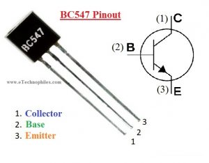
BC547 pinout
This transistor has three pins, starting from left: collector, emitter, and base respectively.

| Pin Number | Pin Name | Description |
| 1 | Collector | This pin act as an inlet as the current enters the transistor from here. The collector is denoted by ‘C’. |
| 2 | Base | This pin controls the transistor biasing. The base is denoted by ‘B’. |
| 3 | Emitter | This pin act as an outlet and the current comes out of the transistor from here. The emitter is denoted by ‘ E’. |
Technical specifications
Some of the important specifications of this transistor are listed below:
- Package-Type: TO-92
- Transistor Type: NPN
- Max Collector Current (IC): 100mA
- Max Collector-Emitter Voltage (VCE): 45V
- Max Collector-Base Voltage (VCB): 50V
- Max Emitter-Base Voltage (VEBO): 6V
- Max Collector Dissipation (Pc): 500 milliwatt
- Max Transition Frequency (fT): 300 MHz
- Minimum & Maximum DC Current Gain (hFE): 110 – 800
- Max Storage & Operating temperature Should Be: -65 to +150 Centigrade
- Low Noise: 2-10 dB
Uses and applications
BC547 is used commonly in:
- The highest transition frequency is 300MHz of this transistor. Thus, it can also be used in RF circuits.
- Amplification of current
- Audio Amplifiers
- Switching Loads < 100mA
- Transistor Darlington Pairs
- Amplifiers like Audio, signal, etc.
- Darlington pair
- Quick switching
- PWM (Pulse Width Modulation)
BC547 transistor as a switch
The regions responsible for a transistor to work as a switch are the Saturation Region and the Cut-off Region. When we apply high enough current at the base of the transistor, it makes a path for the collector current to go through the base towards the emitter.
To use the transistor as a switch, it must be driven into the saturation region with enough base current. A transistor operates as a closed switch under the saturation region.

As soon as a positive signal (in the form of voltage and current) is removed across the base of the transistor, the flow of electric current between the collector and emitter becomes zero. And the transistor behaves like an open switch under the cut-off region.

This simply implies if we apply signal (voltage/current) across the collector and emitter but not across the base, the transistor will not work. But a small signal across the base is enough to make it work.
BC547 as an amplifier
A transistor acts as an amplifier by increasing the strength of a weak signal applied at its base. Transistors work as an amplifier in the active region or linear region. The figure given below shows how to use a transistor as an emitter amplifier.

**Image Source: instrumentationtools
In this region, with the increase in the base current, the collector current also increases proportionally according to the formula:
IC=β IB
Here, IC = collector current
Β = current amplification factor
IB = base current
Thus, a small input signal results in a large output, which implies that the transistor works as an amplifier.
BC547 transistor equivalent
BC547 transistor can be used as an alternative to many transistors:
BC548, BC549, BC636, BC639, 2N2222 TO-92, 2N2222 TO-18, 2N2369, 2N3055 and 2N3904 all are BC547 transistor equivalent.
Datasheet
It comes in two packages- SMD package and the TO-92 package.

Click this link to view the entire DATASHEET
You can find detailed information on the datasheet given above. Specifications and characteristics like Absolute maximum ratings, Block diagrams, biasing methods, and package dimensions can be found in the datasheet.
BC547 TO-92 package dimensions

BC547 transistor projects
You can make many good beginner-level projects using this transistor. Some of the beginner projects are listed below:
Not Gate using a Transistor on Breadboard
NOR Gate using a Transistor on Breadboard
Rain Sensor Alarm using two BC547 Transistor
Where to buy?
You can easily find this transistor in your local electronics store. For online purchases, we recommend this best deal on Amazon:

FAQs
Is BC547 an NPN or PNP transistor?
It is an NPN bipolar junction transistor.
What is the maximum current of a BC547 transistor?
The maximum collector current of a BC547 transistor is 100mA
What is the principle of BC547?
The transistor operates on the principle of bipolar junction transistor (BJT) action, where a small current at the base controls a larger current flow between the collector and emitter terminals. It is an NPN transistor commonly used for amplification and switching applications in electronic circuits.
Thanks very much, I’m building a small signal generator and the schematic called out this part, but they’re not easy to find, your equivalent part numbers were very useful, thanks you.
Best Regards,
Mike
Hi Miked,
We are glad to be of help.