Last updated on March 27th, 2024 at 04:51 pm
The 433 MHz RF transmitter and receiver module is a pair of small RF (i.e. radio-frequency) electronic modules used to send and receive radio signals between any two devices. The transmitter module sends the data from the transmitter end and the Receiver module receives that data at the receiver’s end.

Table of Contents
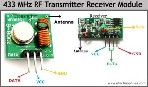
433MHz RF transmitter and receiver module pinout
Transmitter

| PIN Name | Pin Description |
| VCC | Used to power the RF receiver module. |
| GND | Ground pin of the module. Connect it with the controllers and encoder/decoder GND pin. |
| DATA | This is the data pin of the transmitter. It takes the data from the microcontroller or encoder and broadcasts it via the antenna. |
| ANT | The antenna pin is not necessary to use but it is recommended. The module can only operate max 3 meters but its range can be extendable up to 100 meters by using a small hookup wire as an Antenna |
Receiver

| PIN Name | Pin Description |
| VCC | Used to power up the RF receiver module. Unlike the transmitter, the supply voltage of the receiver is 5v. |
| GND | Ground pin of the module. Connect it with the controllers and encoder/decoder GND pin. |
| DATA | These pins output the digital data received. The two center pins are internally connected, so we can use either one of them for data output. |
| ANT | The antenna pin is not necessary to use but it is recommended. The module can only operate max 3 meters but its range can be extendable up to 100 meters by using a small hookup wire as an Antenna |
Transmitter module features
- The Transmitter offers only one-way communication through 433.92MHz frequency at a 1Kb data rate
- It operates at a range of 3-12V which is also the power operating volts of most of the microcontrollers and boards.
- The module uses the ASK (Amplitude Shift Key) modulation method to transmit the data.
- It is one of the very low-cost power effective modules for commercial, hobbyists, and developers.
- 433MHz Transmitter is one of the cheapest RF transmitters and it has a lot of applications and can be used to interface with almost every microcontroller.
Receiver module features
- The RF receiver delivers the output to the data pin in an encoded form.
- The operational voltage range of the module is 5V maximum.
- The receiver’s frequency can be changed using a node present on it.
- It is one of the most popular and cheapest receivers and has low power consumption.
- 433MHz RF receiver module uses the ASK signal as an input.
Working of 433 MHz RF module
Transmitter Working

- This radio frequency (RF) transmitter module uses Amplitude Shift Keying (ASK) and operates at 434MHz. The transmitter module takes serial input through a microcontroller and transmits these signals through RF. The transmitted signals are then received by the receiver module placed at the other end of the source of transmission.

- So when the DATA input pin of Arduino is set to logic HIGH, the oscillator starts generating a constant RF output carrier wave at 434 MHz, and when the logic LOW is applied to the DATA, the oscillator stops producing the RF wave. This technique is known as Amplitude Shift Keying.
Receiver working

- The receiver module receives the data in the form of a signal and sends it to the data pin. The data received by the module is always in an encoded form which can be decoded by either using the microcontroller or the decoder.
- The 433 MHz RF receiver module helps to receive the 433MHz frequency mainly. But it has a node also that can be changed by users for different frequencies. The variable node can be used to adjust the frequency from 315MHz to 433MHz. The receiver just receives the data but to decode and view this data, a microcontroller or decoder is required.
- The RF receiver module comprises an RF-tuned circuit and a couple of operational amplifiers to amplify the carrier wave received from the transmitter. The amplified signal is then further fed to a PLL (Phase Lock Loop). Later it is received by the decoder, which decodes the output stream and gives better noise immunity.
Arduino – 433 MHz RF module connections
Both modules are connected to Arduino as follows:

- VCC – We need to provide positive DC voltage ranges from 3 to 12 volts. So we can connect 5 volts from our Arduino to this pin.
- GND – Connect it to the ground pin of the Arduino.
- DATA IN – Connect it to one of the data pins of Arduino (ex-pin 12)
We can also solder a piece of solid hookup wire to the antenna terminal of the modules. This increases the range of communication from 3m to 100m.
**Full Arduino – 433 MHz RF Module tutorial: Click here
Applications
- Remote Controls
- Automation System
- Wireless Security System
- Sensor Reporting
- Car Security System
- Remote Keyless Entry
FAQs
What is the range of the 433MHz RF transmitter and receiver?
The range of a 433MHz RF transmitter and receiver can vary depending on several factors, but here’s a general guideline:
Ideal conditions (open space, line of sight): Up to 100 meters (330 ft)
Typical conditions (with some walls/obstacles): 30-50 meters (100-165 ft)
Low-power modules: Even shorter ranges (around 10-20 meters or 33-66 ft)
What vehicles use 433 MHz frequency?
This is a 433MHz rubber valve stem TPMS sensor replacement for many Chrysler, Dodge, Jeep, RAM, Subaru, Nissan, GM, Hyundai, and Kia vehicles.
What is a 433MHz RF module?
A 433MHz RF module is a little radio on a chip. It can transmit and receive data wirelessly at 433MHz, like a walkie-talkie for electronics. These cheap, easy-to-use modules are great for short-range wireless projects.